
Diagonal Solar Chimney

a solar chimney and diagonal technology, applied in the direction of wind motors with solar radiation, wind generator control, final product manufacturing, etc., can solve the problems of reducing the economic value affecting the efficiency of solar energy generation, so as to improve the cost/effectiveness of building a 300 to 6000 foot tall diagonal solar chimney, the effect of reducing the cost per kilowatt hour

Inactive Publication Date: 2012-06-21
KLINKMAN PAUL
View PDF8 Cites 9 Cited by
  • Summary
  • Abstract
  • Description
  • Claims
  • Application Information

AI Technical Summary

Benefits of technology

[0014]The cost / effectiveness of building a 300 to 6000 foot tall diagonal solar chimney is improved. Costs of heating air are lowered by preheating the air in many stages, where each stage of heating has unique solar concentration and insulation needs. A number of unique heat sources are tapped. A large-volume chimney lowers costs per kilowatt-hour produced as does running the chimney at a high temperature. Heat is stored for early evening electric generation.

Problems solved by technology

One problem with boiling water by solar methods to create steam is achieving a 100° Celsius minimum boiling temperature.
Unfortunately, the cost of building the 600 foot tower made this particular electricity installation economically unusable.
Also, the 600 foot tower was a minor aviation hazard.
The Manzares concept of gathering and heating local air by erecting a huge acreage of plastic sheets on 10 foot poles is seen as relatively expensive.
The experiment's flat plastic sheeting appears to have been vulnerable to hail, to rain buildup and pondage on top of the plastic, to high wind damage and to rare snow accumulation.
In addition, some commonly used plastics such as polyvinyl chloride will deteriorate in the sun's rays within 4 years.
Unfortunately, the cost of building a 3000 foot tall structure also rises more than proportionally with height.
Cost versus benefits killed this project.

Method used


Image

  • Diagonal Solar Chimney
  • Diagonal Solar Chimney
  • Diagonal Solar Chimney

Examples


Embodiment Construction

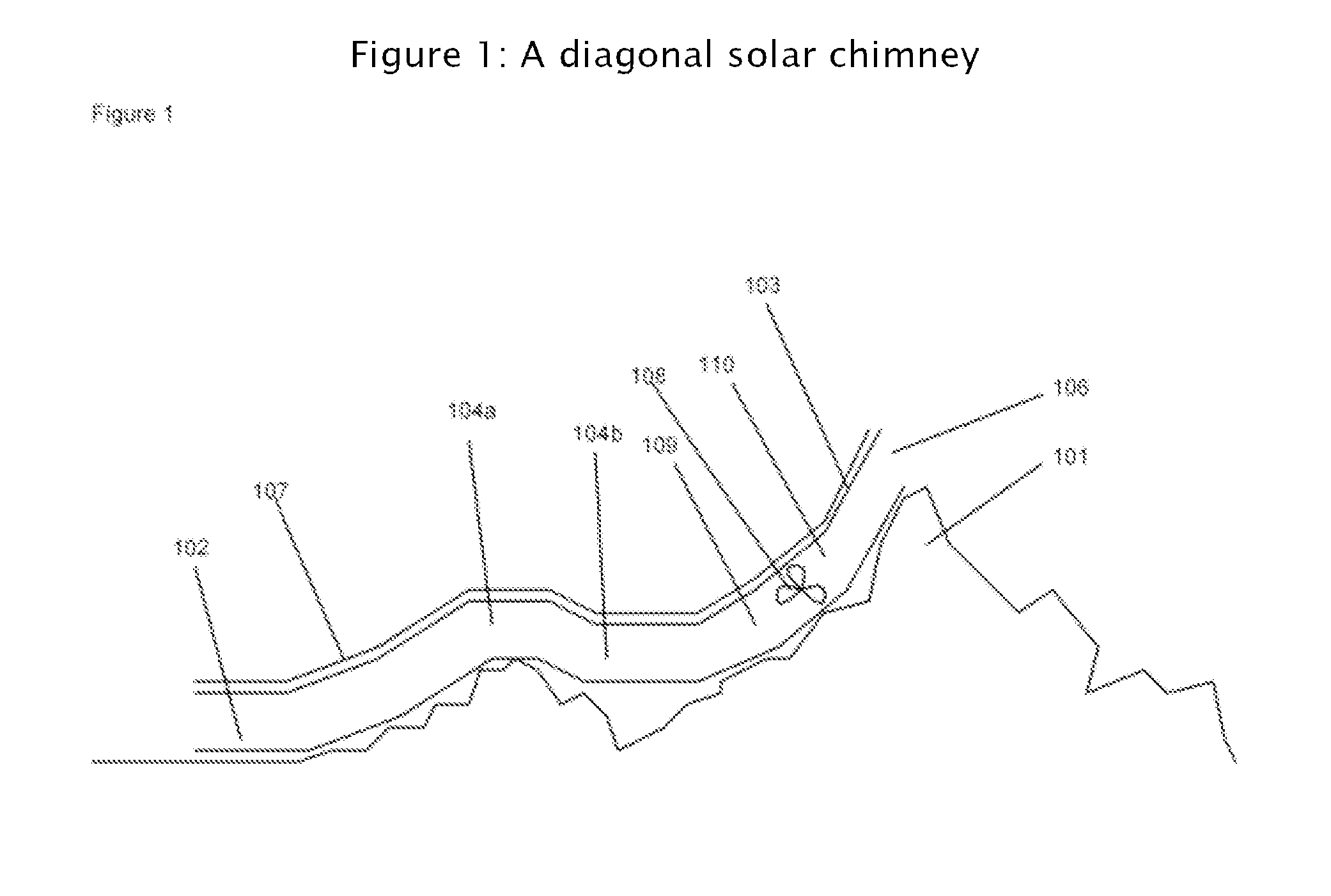
[0038]In the invention's primary embodiment as shown in FIG. 1, a diagonal chimney is laid on the side of sloping terrain (101). Laying the chimney diagonally on existing terrain reduces the engineering cost of supporting an extremely high altitude vertical chimney.

[0039]The chimney's bottom end (102) is substantially lower in elevation than its top end (103). Limited and gentle bends (104a-b) in the chimney may be built as needed to reduce engineering costs on unfavorable terrain, although they also reduce the chimney's available power. In use, air or other gases are continually drawn into the chimney's bottom end. The chimney's top end has an opening (106) to release air.

[0040]In this embodiment the chimney's roof (107) absorbs solar radiation. This heats the incoming air. The warmed air rises up the chimney.

[0041]In this embodiment, a wind turbine (108) is turned by the chimney's draft to produce electricity. This wind turbine placement in the middle of the chimney is better than...


PUM


Abstract

Heated air rises in a long, diagonal chimney up the side of a mountain. The airflow in the chimney turns wind turbines. Air entering the chimney's feeder tubes is heated in stages, where each stage has its own solar concentration and thermal insulation needs. Water, water vapor and air can be preheated as they are shipped to a chimney's lower end. Both low heat for preheating and high heat can be stored for night electricity generation and for continuing the chimney's electric production during cloudy periods. A pressurized chimney or tube may be built with cables pulling the sides outward or holding the sides inward as needed, with separate air fairing and weather protection layers for the chimney or tube. Putting wind turbines in series in a chimney can lessen the air pressure stresses on the chimney's roof.Water vapor rising a considerable elevation in a diagonal chimney will condense, giving up latent heat to the chimney air as it produces distilled water or mountaintop snow. Artificial thunderstorm cells downwind from the chimney may be discouraged through a reduction in negative ions in the outgoing air and through thorough mixing of chimney air with the atmosphere at the chimney's top.

Description

REFERENCES CITED [0001]Claim of Priority: This application for patent claims priority from provisional patent application 61 / 268,374 filed by the inventor on Jun. 10, 2009.U.S. PatentsPatent NumberTitleIssue date7,026,723Air filtering chimney to cleanApr. 11, 2006pollution from a city and generateelectric power6,911,744System and method for convertingJun. 28, 2005wind into mechanical energy6,696,766Atmospheric cold megawatts (ACM)Feb. 24, 2004system TM for generating energy fromdifferences in atmospheric pressure4,497,177Wind generating meansFeb. 5, 19854,367,627Systems for utilizing the energyJan. 11, 1983of a moving air currentFIELD OF THE INVENTION[0002]This invention relates generally to electricity generation, and, more particularly, to solar-driven electricity generation.BACKGROUND OF THE INVENTION[0003]Numerous people in the last 50 years have been involved in technological efforts to generate electricity from sunlight. Some have mounted photovoltaic panels on sun-tracking sw...

Claims


Application Information

Patent Timeline
IPC IPC(8): F03B13/00F01K1/00F03G6/04
CPCF01K27/00F03D1/04F05B2240/13F05B2240/131Y02B10/70Y02B10/30Y02E10/72Y02E10/465F03G6/045Y02B10/20F03D9/007F03D9/35H02S10/12Y02B10/10Y02E10/46Y02E10/50Y02E10/728Y02P70/50
Inventor KLINKMAN, PAUL
Owner KLINKMAN PAUL
Learn More