
Liquid ejecting head unit and manufacturing method thereof

a technology of liquid ejecting head and manufacturing method, which is applied in the direction of metal-working apparatus, power drive mechanisms, printing, etc., can solve the problems of deteriorating image quality more serious adverse effects of recording images or the like, etc., and achieves high positional accuracy and shortening time

Active Publication Date: 2012-06-14
SEIKO EPSON CORP
View PDF3 Cites 15 Cited by
  • Summary
  • Abstract
  • Description
  • Claims
  • Application Information

AI Technical Summary

Benefits of technology

[0012]An advantage of some aspects of the invention is to provide a liquid ejecting head unit and a manufacturing method thereof capable of mounting a plurality of liquid ejecting heads in a shorter time with highly positional accuracy.
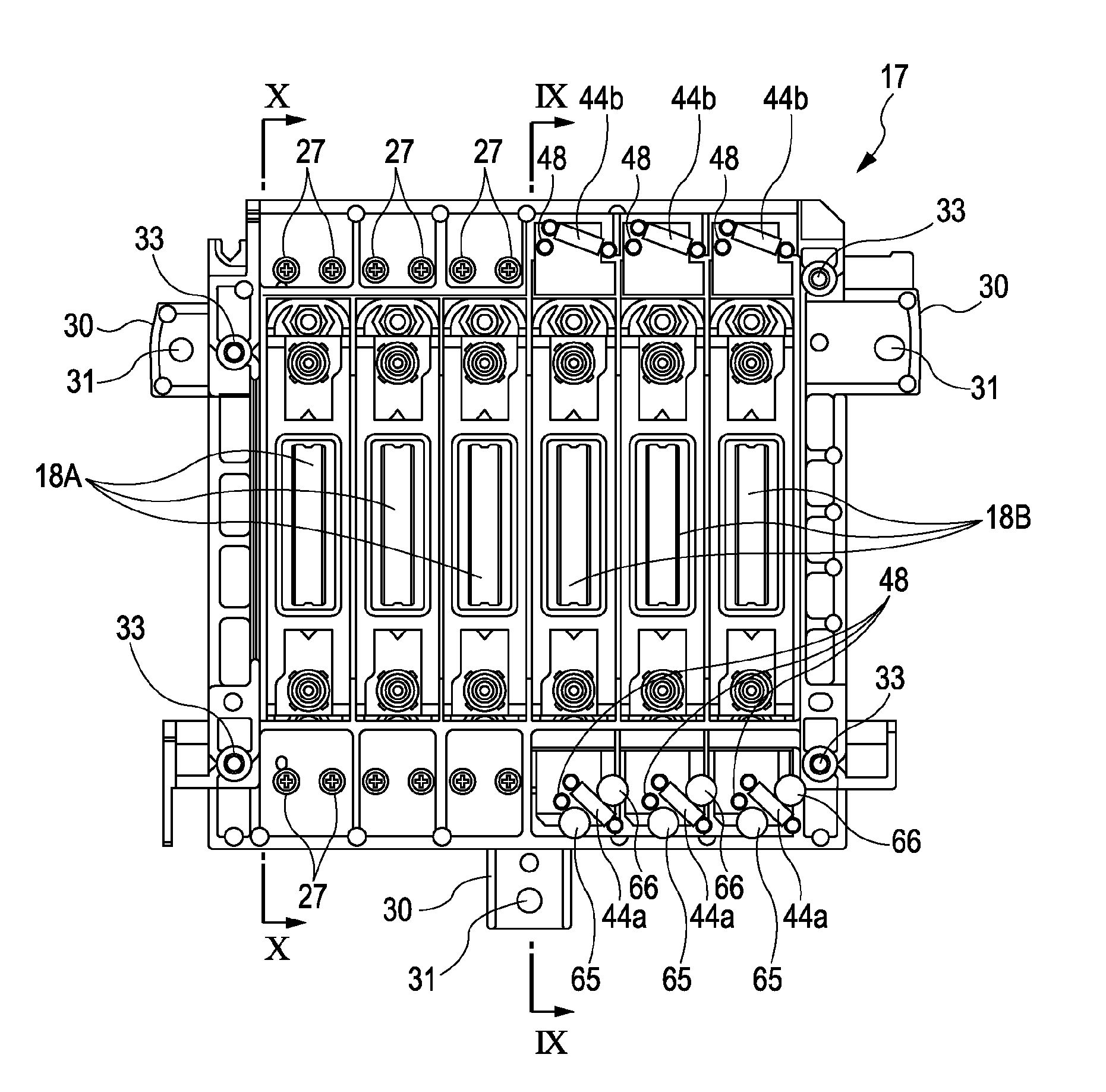
[0014]According to the aspect of the invention, in one side of the first head which has the nozzle row of the same color and forms a set, the one side of first head is fixed in the state of being positioned with respect to the first head mounting portion of the head fixing member so that the target nozzles are disposed in the defined position. On the other hand, in the other side of the second head, based on the landing position in the landing target of the liquid which is ejected from predetermined nozzles of the second head with respect to the landing position in the landing target of the liquid which is ejected from predetermined nozzles of the first head which forms a set, the second recording head is fixed to the head fixing member in the state where the relative position of the second head with respect to the first head is defined by the adjustment mechanism. Therefore, particularly, the positional relationship of the liquid ejecting heads of the same set having the nozzle row of the same color ejecting the liquid is secured with higher accuracy. That is, since the relative position of the liquid ejecting heads of the same set is defined based on an actual liquid landing position, inherent characteristics of every liquid ejecting head such as the inclination of the nozzles to the nozzle formation surface are reflected in the positional relationship of the liquid ejecting heads of the same set. In addition, in the configuration which includes the set of the liquid ejecting head having the nozzle rows of the same color, the landing position deviation between the liquids of the same color can be prevented. Thereby, when an image or the like is recorded with respect to the landing target, deterioration of image quality of a recording image or the like due to the landing position deviation can be suppressed.
[0015]Moreover, compared to the position adjustment method based on the position of the nozzles, the position adjustment method based on the actual landing position on the landing target of the liquid which is ejected from the nozzles needs more adjusting time. However, since the latter position adjustment method having relatively short adjusting time is adopted to one side of the first head forming a set, with regard to the entire liquid ejecting head, the overall adjusting time can be shortened compared to the case in which the former position adjusting method is adopted. As a result, decrease in the productivity or the like can be suppressed.
[0019]According to the liquid ejecting head units, the position adjustment of the reference head with respect to the first head mounting portion is simply and rapidly completed by using the positioning pin, which can contribute to the foreshortening of the adjustment time.

Problems solved by technology

Thereby, there is a concern that an adverse effect may occur in the image quality of the recording image or the like.
As a result, variation in the landing position of the ink with respect to a recording medium such as a recording sheet occurs, and there is a concern that image quality of a recording image or the like may deteriorate.
In particular, as the above-described configuration, if variation of the landing position occurs in the recording heads which are symmetrically disposed to the sub-carriage and constitute a set of the same color, more serious adverse effect may occur in the image quality of the recording image or the like.
However, when compared to the method in which the mounting position of the recording head on the basis of the position of the nozzles is adjusted, the adjusting method needs many more adjusting times, and there is a problem in that a disadvantage from the standpoint of productivity occurs.
In addition, the above problems are generated in not only an ink jet type recording apparatus on which the recording head ejecting ink is mounted but also other liquid ejecting head units adopting a configuration which fixes a plurality of liquid ejecting heads to a head fixing member and a liquid ejecting apparatus including the liquid ejecting head unit.
Moreover, compared to the position adjustment method based on the position of the nozzles, the position adjustment method based on the actual landing position on the landing target of the liquid which is ejected from the nozzles needs more adjusting time.

Method used


Image

  • Liquid ejecting head unit and manufacturing method thereof
  • Liquid ejecting head unit and manufacturing method thereof
  • Liquid ejecting head unit and manufacturing method thereof

Examples


Embodiment Construction

[0042]Hereinafter, embodiments according to the invention will be described with reference to the accompanying drawings. In addition, the embodiments described below are preferably specified examples and variously limited. However, the range of the invention is not limited to the embodiments unless the gist in which the invention is particularly limited is described in the description below. Moreover, in the description below, an ink jet type recording apparatus (hereinafter, referred to as a “printer”) is described as an example of a liquid ejecting apparatus.

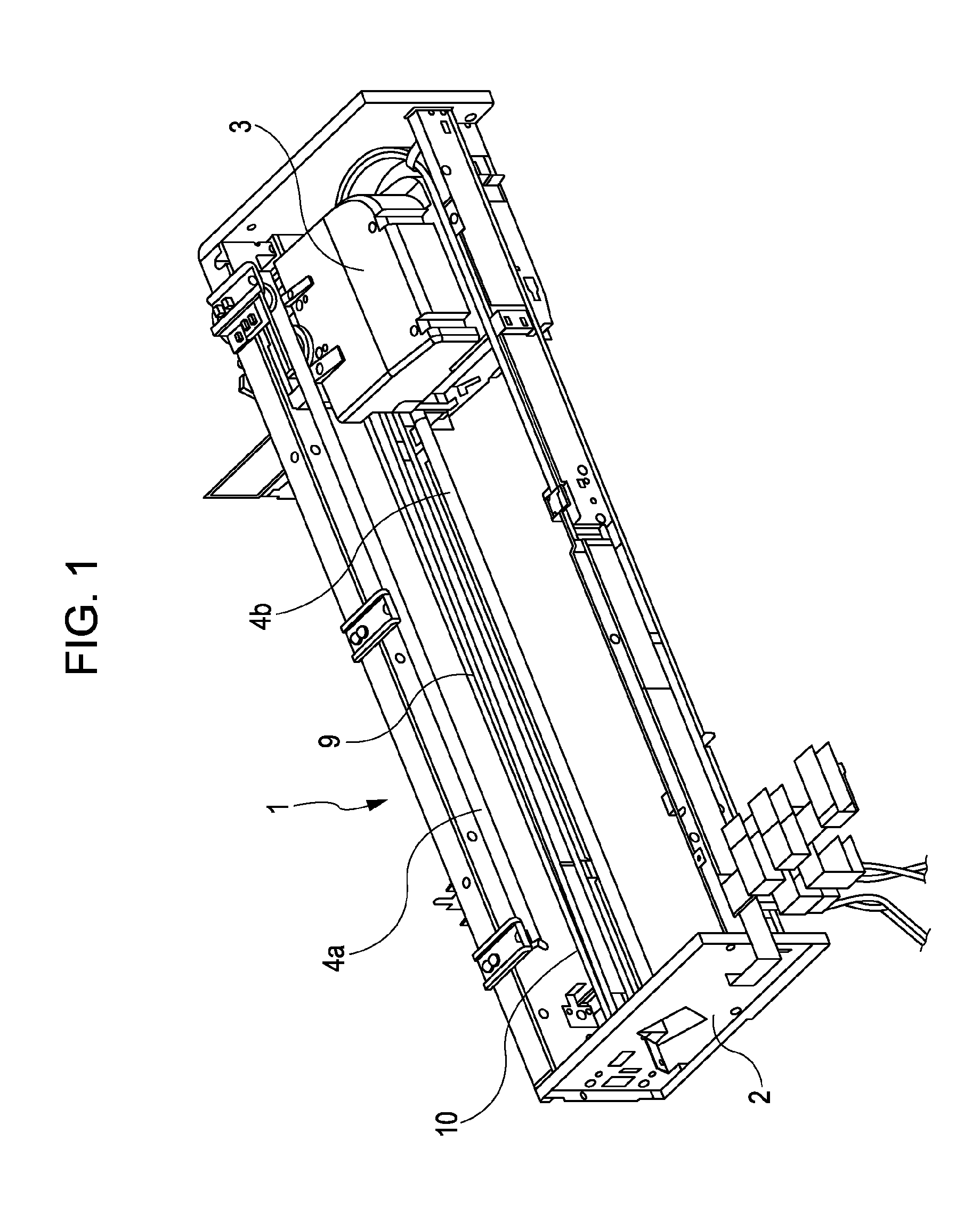
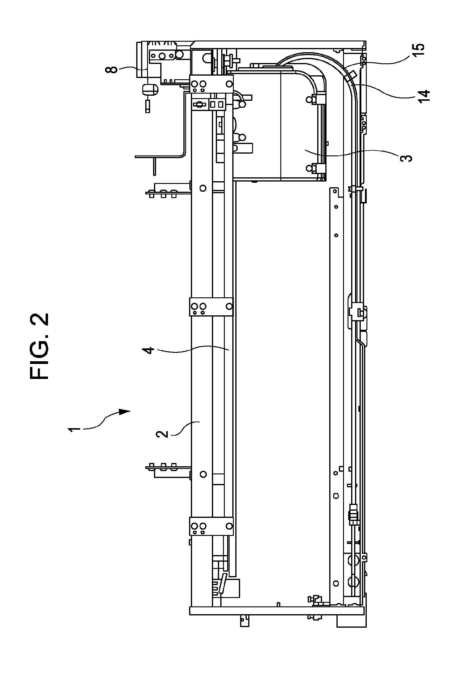
[0043]FIG. 1 is a perspective view showing a portion of an inner configuration of a printer 1, and FIG. 2 is a plan view of the printer 1. The illustrated printer 1 ejects ink which is a kind of liquid toward a recording medium (a target on which to be landed) such as a recording sheet or a film. The printer 1 mounts a carriage assembly 3 (a kind of a head unit holding member) so as to be reciprocated in a main scanning direct...


PUM


Abstract

A sub-carriage includes a first head mounting portion and a second head mounting portion. The second head mounting portion includes at least a portion of constitution members of an adjustment mechanism which adjusts a position of the second head, a first recording head of one side of the same set is fixed in a state of being positioned to the first head mounting portion so that the nozzles are disposed in a defined position, and a second recording head of the other side is fixed to the second head mounting portion in a state where the relative position to the first recording head is defined by the adjustment mechanism based on a landing position in a recording medium of ink ejected from predetermined nozzles of the second recording head with respect to a landing position in a recording medium of ink ejected from predetermined nozzles of the first head.

Description

[0001]The entire disclosure of Japanese Patent Application No: 2010-275423, filed Dec. 10, 2010 is expressly incorporated by reference herein.BACKGROUND[0002]1. Technical Field[0003]The present invention relates to a liquid ejecting head unit which is used in a liquid ejecting apparatus such as an ink jet type recording apparatus and a manufacturing method thereof, and particularly, to a liquid ejecting head unit capable of mounting a plurality of liquid ejecting heads with highly positional accuracy and a manufacturing method thereof.[0004]2. Related Art[0005]A liquid ejecting apparatus includes a liquid ejecting head capable of ejecting liquid as a droplet, and various liquids are ejected from the liquid ejecting head. For example, as a representative of the liquid ejecting apparatuses, an image recording apparatus such as an ink jet type recording apparatus (printer) can be listed, in which an ink jet type recording head (hereinafter, referred to as a “recording head”) is provide...

Claims


Application Information

Patent Timeline
IPC IPC(8): B41J2/21B23P17/00
CPCB41J25/34Y10T29/49401B41J2202/19B41J25/001B41J25/003B41J2202/20
Inventor HAGIWARA, HIROYUKIKANAYA, MUNEHIDEHIRUMA, DAISUKE
Owner SEIKO EPSON CORP
Learn More