Switching power supply and display device provided with same
a technology of switching power supply and display device, which is applied in the direction of electric variable regulation, process and machine control, instruments, etc., can solve the problems of poor total conversion efficiency, insufficient stabilization of the whole power efficiency and output voltage, and technology disclosure, etc., to achieve the effect of reducing and thinning the devi
- Summary
- Abstract
- Description
- Claims
- Application Information
AI Technical Summary
Benefits of technology
Problems solved by technology
Method used
Image
Examples
first embodiment
[0038]A first embodiment of the present invention will be explained with reference to FIGS. 1 to 9. An explanation will be given of a circuit configuration of the first embodiment at first.
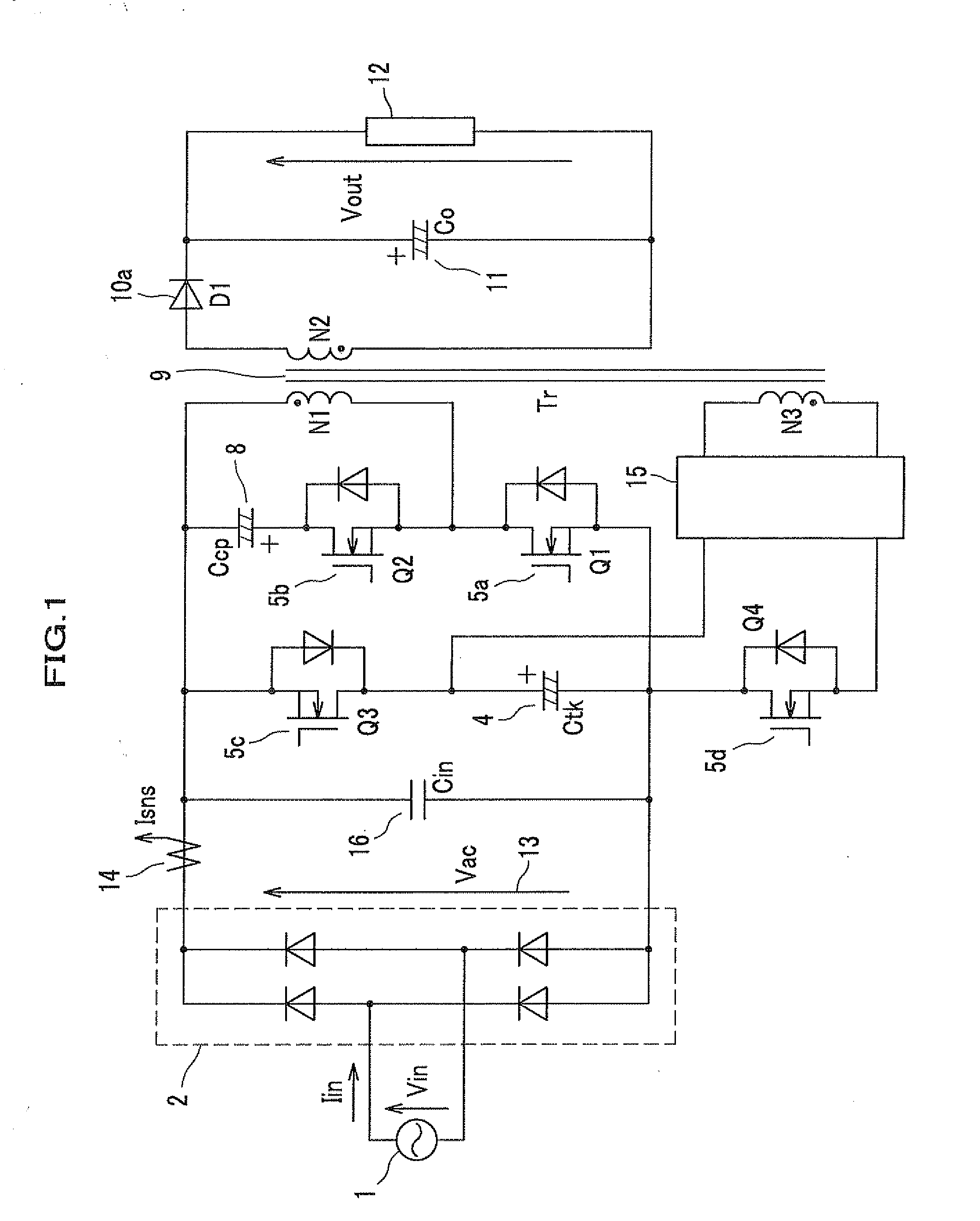
[0039]FIG. 1 is a circuit diagram showing a configuration of a switching power supply according to the first embodiment of the present invention.
[0040]As shown in FIG. 1, an AC power 1 by an AC power supply 1 is subjected to full-wave rectification (see FIG. 4, a full-wave rectification waveform 13) through a diode bridge 2. An input capacitor 16 (Cin) is connected between the DC-side positive and negative terminals of the diode bridge 2. The input capacitor 16 is for filtering, and has a capacitance of several μF.
[0041]The diode bridge 2 (a rectification function) and the input capacitor 16 (a filtering function, a smoothing function) configure first rectification-smoothing means.
[0042]A current between the diode bridge 2 and the input capacitor 16 is detected as an input current Isns having unde...
second embodiment
[0139]Next, an explanation will be given of a second embodiment with reference to FIG. 11.
[0140]FIG. 11 shows a specific circuit configuration of the charging circuit 15 shown in FIG. 1 in more detail as an embodiment.
[0141]The anode of a diode 10b (D2) is connected to the end (an opposite side of the black dot) of the third winding N3 of the insulation transformer 9, and a capacitor 48 is connected between the cathode of the diode 10b and the beginning (the black dot) of the secondary winding N2. The diode 10b has the cathode connected to the positive terminal of the instant power-suspension compensating capacitor 4 through a coil 49, and the negative terminal is connected to the negative terminal of the instant power-suspension compensating capacitor 4 through the power MOSFET 5d (the switching device Q4).
[0142]The power MOSFET 5d is an N-type (N-channel) device, has the drain connected to the negative terminal of the instant power-suspension compensating capacitor 4, and the sour...
third embodiment
A
[0151]FIG. 12A shows a simplest configuration as a function of the output voltage detector. That is, at the secondary side of the insulation transformer 9 (see FIG. 1), an output voltage (a voltage across both terminals of the output smoothing capacitor 11) is divided by a resistor 501 and a resistor 502, input into an ADC (Analog to Digital Converter, an A / D converter IC) 53 and is converted into a digital signal with pulse strings, and such a digital signal is transmitted to the primary side of the insulation transformer 9 (see FIG. 1) by a photocoupler 52, thereby causing the controller 51 to receive the signal.
[0152]In this case, in general, in order to transmit at least a clock signal and a control signal CS for a control to the ADC, and to receive a result as a serial signal, fast-speed photocouplers by what corresponds to at least three channels are necessary.
[0153]The reason why the photocoupler 52 is used is to insulate between the primary side and the secondary side in or...
PUM
 Abstract
Description
Claims
Application Information
 - R&D
- Intellectual Property
- Life Sciences
- Materials
- Tech Scout
- Unparalleled Data Quality
- Higher Quality Content
- 60% Fewer Hallucinations
Browse by: Latest US Patents, China's latest patents, Technical Efficacy Thesaurus, Application Domain, Technology Topic, Popular Technical Reports.
© 2025 PatSnap. All rights reserved.Legal|Privacy policy|Modern Slavery Act Transparency Statement|Sitemap|About US| Contact US: help@patsnap.com


