Wireless radiation sensor

a wireless radiation sensor and sensor technology, applied in the field of wireless radiation sensors, can solve the problems of complex electronic components of devices, high cost, and high cost of radiation detection methods, and achieve the effects of minimizing design costs and time-to-market, minimizing per-part costs, and maximizing the cost-effectiveness of development and manufacturing

Inactive Publication Date: 2012-06-14
NATIONAL YANG MING UNIVERSITY
View PDF4 Cites 1 Cited by
  • Summary
  • Abstract
  • Description
  • Claims
  • Application Information

AI Technical Summary

Benefits of technology

[0015]The design of the modules, disclosed herein, in the present invention, can be based upon components that are used for unrelated applications, to maximize the cost-effectiveness of development and manufacturing.
[0016]Technical advantages are gained by using off-the-shelf components that require only slight modification, with minimal design costs and time-to-market. Commodity components, such as DVD / CD read / write heads, can be used to minimize the per-part costs. Well-established wireless communication-based data transfer and analysis methods can be used to minimize design costs, and maximize reliability, safety, and ease-of-use.
[0017]The invention has the ease-of-use advantage that it does not require invasive surgery. Meanwhile, no specialized technician is required to operate the sensor. A patient can easily operate the sensing module individually. This fact is especially important for patients with psychological or moral issues regarding diagnosis by others, for example, in the courses of breast cancer checkups. The collected data can be analyzed using either an automated computer program or an expert at any time, and no dedicated laboratory is required.

Problems solved by technology

However, these methods of radiation detection require well-trained operators and an appropriately equipped laboratory.
Most of the devices have complex electronic components and are bulky.

Method used


Image

  • Wireless radiation sensor
  • Wireless radiation sensor
  • Wireless radiation sensor

Examples


embodiment 1

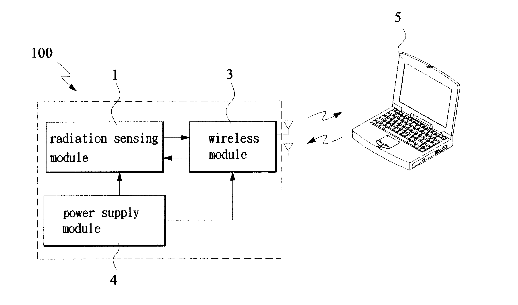
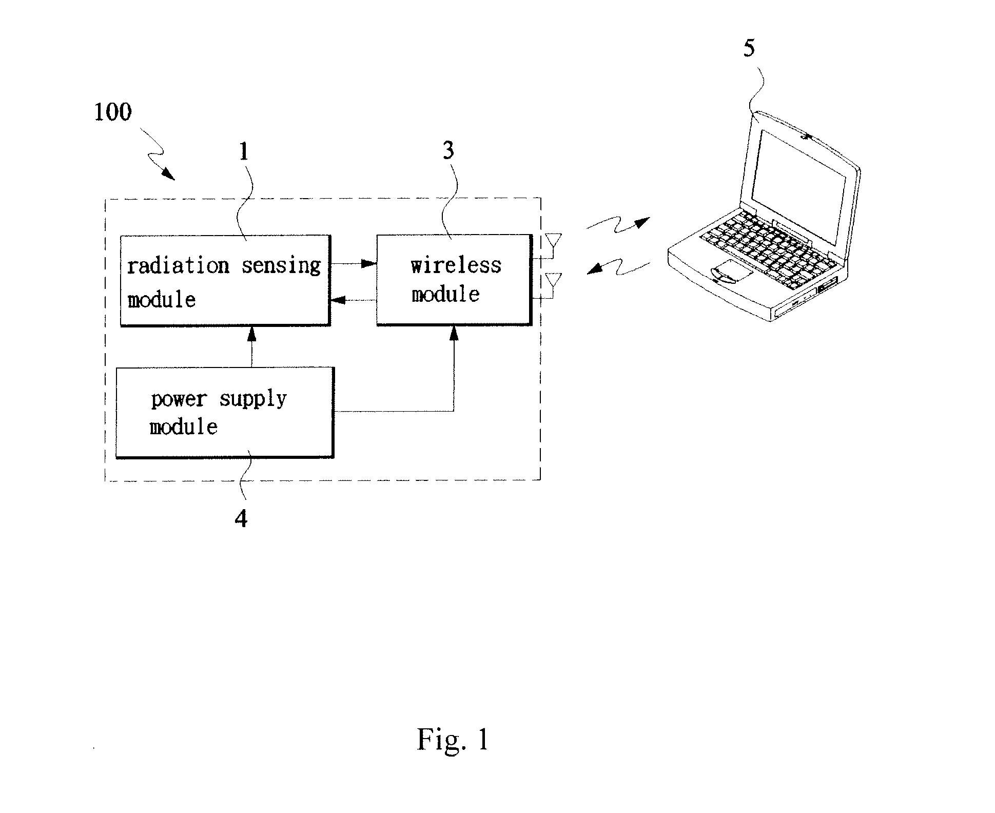
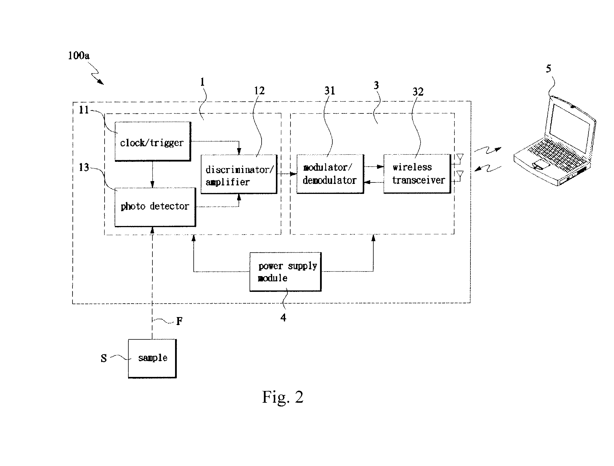
[0023]With reference to FIG. 2, the wireless radiation sensor 100a comprises an optimal module 1, a wireless module 3, and a power supply module 4.

[0024]The radiation sensing module 1 including a clock / trigger 11, a discriminator / amplifier 12 and a photo detector 13 (or a radiation detector). The clock / trigger 11 is adapted to generate a timebase and drives the components of the photo detector 13, such as laser diodes and APD. The discriminator / amplifier 12 is adapted to receive the output signal from the APD, which is gated by a signal from the clock / trigger 11, which can amplify and transmit the pulsed signal to the wireless module 3. Generally, laser beams are emitted onto a sample S by an external laser source, and the fluorescence signals F of the sample S, excited by these laser beams, can be detected by the radiation sensing module 1 to generate pulsed signals. Preferably, the laser beams and the detected fluorescence signals are in the visible (VIS) and near-infrared (NIR) s...

embodiment 2

[0029]FIG. 4 shows the second embodiment of the wireless radiation sensor 100b. As shown in the system diagram, the wireless radiation sensor 100b including an radiation sensing module 1, a wireless module 3 and a power supply module 4, of which the radiation sensing module 1 is further integrated with a microcontroller module 2, which is adapted to process the pulsed signals. The radiation sensing module 1, microcontroller module 2, wireless module 3 and power supply module 4, are functionally similar to those described in the first embodiment. Only the microcontroller module 2 is characterized below.

[0030]The microcontroller module 2 including an analog / digital (A / D) conversion unit 21 and a digital signal processing (DSP) unit 22. The microcontroller module 2 is electronically connected to the wireless module 3, and is capable of processing the pulsed signals. After signal processing, the pulsed signals are wirelessly transmitted by wireless module 3 to a computer for data analys...


PUM


Abstract

A wireless radiation sensor is disclosed. The wireless radiation sensor including a radiation sensing module capable of detecting radiation and generate pulsed signals; a wireless module (which can be a passive component/high-frequency antenna) that is connected to the radiation sensing module, which is capable of transmitting the pulsed signals without signal processing, which are received by a computer for data analysis, and a power supply module that is connected to the radiation sensing module and/or wireless module (if an active transmitting module is used) to supply required electricity.

Description

CROSS-REFERENCED TO RELATED APPLICATIONS[0001]This Non-provisional application claims priority under 35 U.S.C. §119(a) on Patent Application No(s). [099143334] filed on Dec. 10, 2010 Republic of China, the entire contents of which are hereby incorporated by reference.FIELD OF THE INVENTION[0002]This present invention is a radiation sensing device, and, in particular, is a wireless radiation sensor.BACKGROUND OF THE INVENTION[0003]In the field of radiation detection, radiation of various wavelengths, comprising infrared light, ultraviolet radiation, visible light, X-ray radiation, alpha particles, beta particles, and gamma rays can be detected. Various designs fulfill different requirements, for use in industry, the military or medical science.[0004]For example, Geiger counters are used to detect ionizing radiation. An inert gas-filled tube (usually filled with helium, neon or argon with added halogens) briefly conducts electricity when a particle or photon of radiation makes the gas...

Claims


Application Information

Patent Timeline
Patent Type & Authority Applications(United States)
IPC IPC(8): G01T1/00
CPCA61B6/4258A61B6/4405G01T7/00A61B6/56A61B6/502
Inventor KAO, FU-JENKUO, BO-JAUHSIEH, I-TEDELLWIG, THILO
Owner NATIONAL YANG MING UNIVERSITY
Why Eureka
Try Eureka