Adjustable guide in computer assisted orthopaedic surgery

a technology of orthopaedic surgery and adjustable guide, which is applied in the field of adjustable guide in computer assisted orthopaedic surgery, can solve the problems of generating time and logistics problems, adding time and cost to the procedure, and major drawbacks, and achieves easy reading and adjustment, affecting the longevity of the implant, and more flexibility in the adjustment mechanism

Active Publication Date: 2012-06-07
BLUE ORTHO
View PDF64 Cites 50 Cited by
  • Summary
  • Abstract
  • Description
  • Claims
  • Application Information

AI Technical Summary

Benefits of technology

[0032]In the fourth step, the adjustable guide is prepared for surgery from the output file obtained at the previous step. This preparation can be performed by an assistant before the first incision of the patient. It is possible to adjust the screws manually using a graduation on each screw. But this process is time consuming and prone to error. Preferably, a dedicated screw driver is used. In a preferred embodiment, the screw length is easy to read and adjust. For that purpose, the dedicated screw driver contains an external tube that comes into contact with the exterior part of the adjustable guide by using a spring that pushes the tube towards the guide and it contains a tip that can fit with the head screws at a unique depth such that when the screwdriver tip is engaged on the screw head, the length of the screw is uniquely determined with respect to the external surface of the guide. Therefore, the relative displacement between the external tube and the screwdriver tip is the screw length with a known offset that can be subtracted. This relative displacement can be measured and read electronically like for any standard digital calipers square. It can be output to a computer with a display monitor. The user reads the value for each screw number and adjusts the screw length manually until it matches precisely the desired target. In a second preferred embodiment, the dedicated screwdriver is motorized and communicates with a computer through a wire connection including power supply, or preferably through wireless communication with batteries. The readings from the electronic length sensor are sent to the computer. For a given screw, the motors are activated in one or other direction until the readings match the desired value. Some standard optimized control can be implemented to speed the convergence of each screw towards its target position. In addition, the screw number can be detected automatically by using a variety of recognition techniques implemented in the screw heads, such as optical, inductance, magnetic detection technologies. This embodiment has the advantage that the program of the computer can check that all screws have been adjusted and none is missing. When all screws have reached their target position, the adjustable guide can be positioned by the surgeon on the patient and the surgeon can estimate if the fit is good or not, using tactile sensing. The adjustable guide is sterile. It is preferably a metallic instrument that can be sterilized in autoclave or a disposable plastic instrument pre sterilized for single use.
[0033]In the fifth step, a navigation system is used to check that the guide is in a correct location. For instance, for a femoral guide, once the adjustable guide is locked in a unique position on the femur, a tracker is attached to it and the surgeon performs a standard hip pivot kinematics from which any standard image free navigation system can extract the hip center. The relationship between the tracker and the adjustable guide is known precisely. The determination of the hip center in the coordinate system of the adjustable guide is used to check that the distal cut will be orthogonal to the axis passing through the knee center determined as a point, fixed or variable, in the coordinate system of the adjustable guide and the hip center, or that a predefined angle selected by the surgeon has been reached. This step is extremely important since a small deviation in the contact points of the adjustable guide can lead to several degrees of error on that angle, which is known to impact the longevity of the implant. This process is repeated until the values match the desired angle. In addition, the surgeon can decide to adjust the planning position intra-operatively to take into account new information such as ligament balancing and desired gaps between the femur and the tibia at several flexion angles of the leg, obtained for instance with the help of a tensor mechanism. It can be also decided during surgery to change the size of the prosthesis. The computer will indicate precisely which screws will need to be adjusted since the computer program can estimate the location of the surface of bone and cartilage from the registered position of the adjustable guide. The computer can also indicate if a bigger or smaller size of the adjustable guide is necessary to reach the desired target. Once the guide is in its final position, the surgeon inserts pins in the holes and the guide is removed. Cutting blocks are inserted on the pins and the surgery can proceed as usual. Several mechanical architectures and designs can be implemented to introduce more flexibility in the adjustment mechanism as it will be described in the detailed description.

Problems solved by technology

Such patient specific guides require specific machining and a complex process where many errors can occur, which adds time and cost to the procedure.
This is a major drawback.
Such templates are usually disposable and machined for each patient which generates time and logistics issues before surgery.
This is a major drawback of navigation systems.
Surgeons and patients are more and more reluctant to make additional holes into the bone for navigation purpose, because it creates additional scars, it increases the fragility of the bone and it adds time to the procedure.
In addition, image free navigation systems do not offer the possibility to make a predetermination of the size of the implant preoperatively.
In addition, some surgeons have difficulties to adjust the cutting blocks to predefined values, which require additional time and efforts.

Method used


Image

  • Adjustable guide in computer assisted orthopaedic surgery
  • Adjustable guide in computer assisted orthopaedic surgery
  • Adjustable guide in computer assisted orthopaedic surgery

Examples


Embodiment Construction

[0044]The tracking technology of trackers and navigation systems is independent of the invention, provided that the trackers are tracked in real-time by the navigation system. It includes, but is not limited to optical active technology, with active infrared Light Emitting Diodes (LEDs) on trackers, optical passive technology (with passive retro-reflective markers on trackers), mechanical passive arms with encoders, radio-frequency measurements, gyro meters and accelerometers or magnetic technology. Those tracking technologies are known as prior art of navigation systems for surgery.

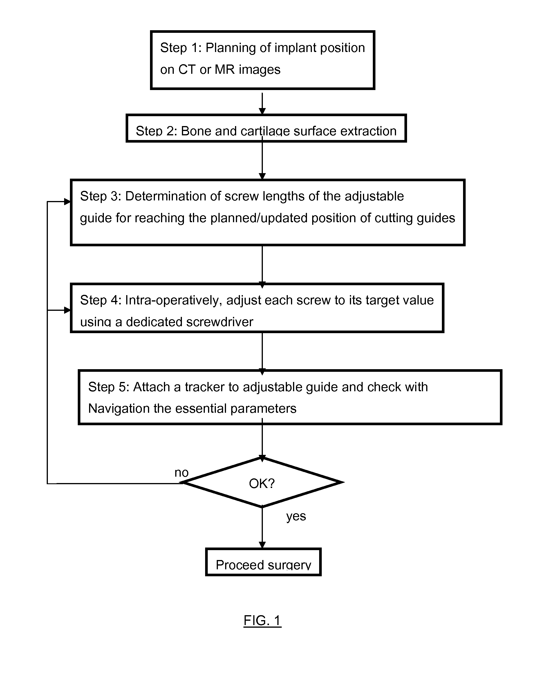
[0045]FIG. 1 presents the successive steps of the method according to the invention.

[0046]The first step of the method consists in acquiring patient images that can be CT or MR images and then performing a surgical planning of an implant position on those images using a computer with display and man machine interactions. The patient images can also be provided by intra-operative three-dimensional fluoros...


PUM


Abstract

The present invention relates to a surgical navigation device, for the purpose of adjusting cutting planes to a desired position with respect to a bone of a patient, the device comprising:an adjustable guide (15) that contains several adjustable screws (1) that create contact points with the surface of the bone or cartilage such that the guide fits to the bone in a unique position calculated such that the holes and cutting blocks of the adjustable guide fit with the position planned on preoperative CT or MR images of the patient,a dedicated screwdriver (7) to adjust automatically the screws (1) to their target length,a navigation system used to check the correct position of the adjustable guide with respect to essential anatomical points and if necessary means to correct the positions of the adjustable screws.

Description

PURPOSE OF THE INVENTION[0001]The present invention relates to a method and device that accelerates the placement of cutting guides in orthopaedic surgery, such as for instance total knee arthroplasty, uni knee arthroplasty or knee revision procedures, by taking the advantage of pre-operative patient images and intra-operative navigation systems and avoiding the drawbacks of patient specific guides manufactured as solid blocks, which do not offer enough flexibility, and avoiding drawbacks of navigation systems, which usually require additional steps in the surgical workflow.BACKGROUND OF THE INVENTION[0002]It is known that patient specific guides are generated from preoperative CT (Computed Tomography) or MR (Magnetic Resonance) images, such that after surgical planning based on patient images, rapid machining of a specific guide is performed. The resulting guide is a solid block which is positioned in a supposedly unique and reproducible manner on the patient bone or cartilage surf...

Claims


Application Information

Patent Timeline
IPC IPC(8): A61B17/56
CPCA61B17/155A61B17/157A61B17/8875A61B2019/508A61B19/5244A61B2017/00398A61B2019/462A61B19/50A61B34/20A61B2090/062A61B34/10A61B2034/108A61B17/15A61B17/151A61B17/152A61B17/154
Inventor BOYER, ANTHONYLAVALLEE, STEPHANE
Owner BLUE ORTHO
Why Eureka
Try Eureka