
Pitch system balancing

a technology of balancing system and wind turbine blade, which is applied in the direction of propellers, propulsive elements, water-acting propulsive elements, etc., can solve the problems of difficult to close a hole in a very flexible glass fibre blade shell, additional manufacturing costs, and turbine problems, and achieves the effect of easy method for removing balancing weigh

Inactive Publication Date: 2012-05-31
ENVISION ENERGY DENMARK
View PDF10 Cites 6 Cited by
  • Summary
  • Abstract
  • Description
  • Claims
  • Application Information

AI Technical Summary

Benefits of technology

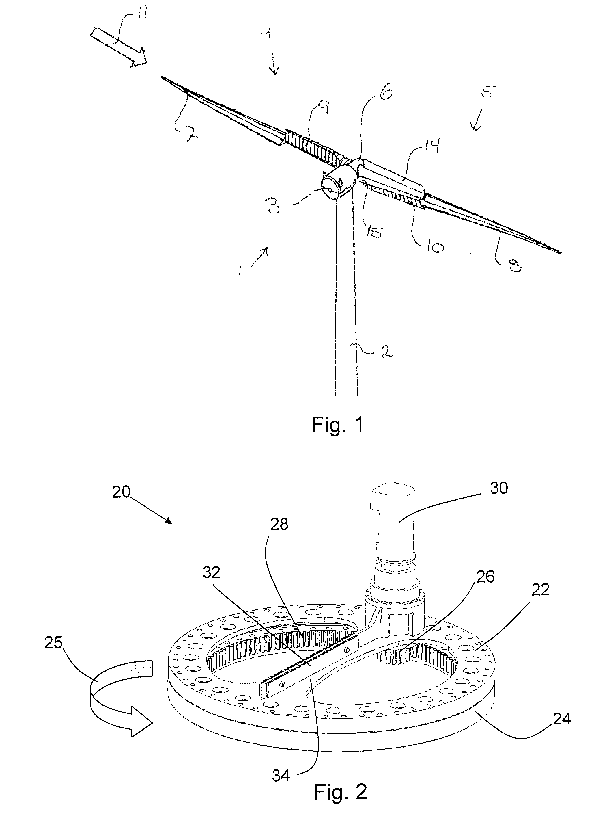
[0010]As the pitch system can be used to hold the balancing weights necessary to balance the rotor blade, this allows for ease of interchange of balancing weights (i.e. weights can be relatively easily added or removed to the pitch system), improved structural stability of the rotor blade (no fundamental alterations need to be made to the blade body or profile to accommodate the weights), and improved safety (as balancing weights are no longer provided in the blade tip, there is reduced chance that the balancing weights may be thrown free of the blade, e.g. during hazardous weather conditions).
[0012]Preferably, said at least one balancing element coupled to said pitch system on said partial pitch rotor blade is a multi position able balancing element. With a multi position able balancing element it is possible to position the same balancing element in different positions on the pitch system. This allows for not only balancing the blade with respect to e.g. the weight in the tip end and at the pitch system, it also allows for balancing the rotor blade in a plane orthogonal to the length of the blade.
[0022]As the blade extender is hollow, and as the balancing elements can be mounted to the pitch system (which is exposed to the interior of the assembled blade), this means that a worker may easily enter the interior of the assembled blade to add or remove balancing weights to the pitch system as needed. This removes any complicated drilling of holes etc. in the body of the blade to add balancing weights, and accordingly allows for improved structural stability of the blade construction. Accordingly, said step of providing a method for balancing a partial pitch rotor blade may comprise assembling said partial pitch rotor blade, or providing an assembled rotor blade.
[0025]Furthermore, in the case of damaged or wrongly balanced rotor blades, the system provides for a relatively easy method for removing balancing weight as required.

Problems solved by technology

Otherwise the turbine may have problems during start-up and operation.
In practice, it is relatively difficult to close a hole in a very flexible glass fibre blade shell.
Also, a special chamber is required for the balancing weight, which results in additional costs for manufacture.
Furthermore, there are potential risks that balancing weights may fall off and destroy the internal blade, or in worst case be thrown several hundred meters away from the turbine.

Method used


Image

  • Pitch system balancing
  • Pitch system balancing
  • Pitch system balancing

Examples


Embodiment Construction

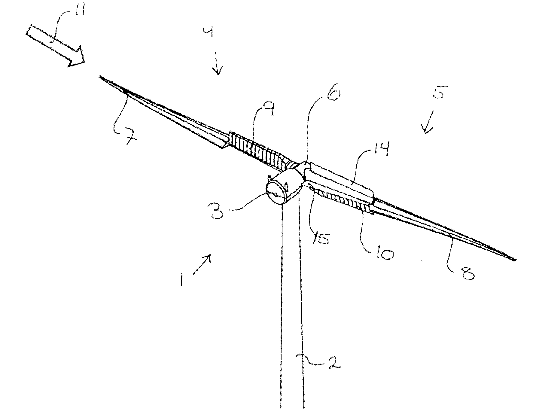
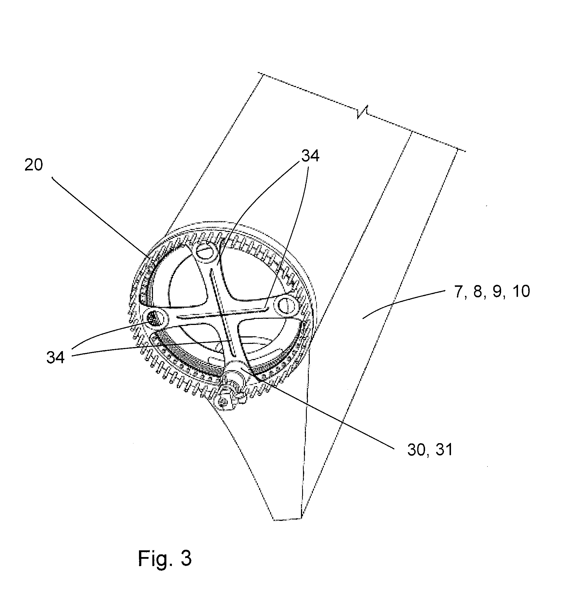
[0006]Accordingly, there is provided a partial pitch rotor blade for a wind turbine, said rotor blade having a length of at least 35 metres, the blade comprising:[0007]an inner blade portion;[0008]an outer blade portion;[0009]a pitch system provided between said inner blade portion and said outer blade portion, said pitch system comprising at least a first flange in connection with a first part of a bearing and at least a second flange in connection with a second part of said bearing and further comprising a pitch mechanism, said pitch mechanism being operable to pitch said outer blade portion relative to said inner blade portion, wherein said pitch system comprises at least one balancing element coupled to said pitch system to balance said partial pitch blade.

[0010]As the pitch system can be used to hold the balancing weights necessary to balance the rotor blade, this allows for ease of interchange of balancing weights (i.e. weights can be relatively easily added or removed to the ...


PUM

PropertyMeasurementUnit
lengthaaaaaaaaaa
lengthaaaaaaaaaa
weightsaaaaaaaaaa

Abstract

A balancing method and system for a partial pitch rotor blade for a wind turbine is described. Balancing elements are mounted to the pitch system of the rotor blade, which remove the need for complicated balancing operations to be performed which may affect the structural stability of the rotor blade body. A method is described wherein a suitable compensating balancing weight for mounting to the pitch system may be used, the weight chosen based on the known tip and root weights of standard blade extender and rotor blade parts used.

Description

FIELD OF THE INVENTION[0001]The present invention relates to a system and method for balancing a wind turbine blade, in particular a partial pitch wind turbine blade.BACKGROUND OF THE INVENTION[0002]In wind turbine construction, a two or a three bladed rotor must be accurately balanced. Otherwise the turbine may have problems during start-up and operation. Usually, some balance weights are placed close to root of the blade and close to tip also. Recently, the preferred method is to add weight to the tip only, in order to achieve the same self weight moment for all blades.[0003]An example of a known balancing system is seen in Danish Patent DK 176901 B1. This involves the formation of holes in the body of the blade for the addition of balancing weights along the blade. In practice, it is relatively difficult to close a hole in a very flexible glass fibre blade shell. Also, a special chamber is required for the balancing weight, which results in additional costs for manufacture. Furth...

Claims


Application Information

Patent Timeline
Patent Type & Authority Applications(United States)
IPC IPC(8): F03D7/02B23P15/00
CPCF03D7/0228Y02E10/723Y10T29/49336F03D1/008F05B2260/966F03D13/35Y02E10/72
Inventor GRABAU, PETERFRIEDRICH, MICHAELSORENSEN, CARSTEN BENDIX
Owner ENVISION ENERGY DENMARK
Learn More