Image display apparatus

a technology of image display and display device, which is applied in the direction of lighting and heating apparatus, optics, instruments, etc., can solve the problems of inability to produce high-quality images, weak red color laser light source output, and deterioration of image quality, so as to prevent image quality deterioration, stably obtain laser light output, and reduce the effect of red color laser light sour

Inactive Publication Date: 2012-05-31
PANASONIC CORP
View PDF5 Cites 5 Cited by
  • Summary
  • Abstract
  • Description
  • Claims
  • Application Information

AI Technical Summary

Benefits of technology

[0008]An advantage of the present invention is to provide an image display apparatus that inhibits image quality deterioration.
[0009]The image display apparatus according to the present invention includes a case having an air inlet port and an exhaust port. The case has an air passage that connects the air inlet port and the exhaust port and channels air. The image display apparatus according to the present invention further includes an air blower that is in the air passage in the case and channels the air, and a plurality of laser light sources housed in the case and each having a heat dissipator that releases heat generated by itself, and each having a light emission wavelength different from one another. At least a part of the heat dissipator of a laser light source having the lowest upper limit of an operating temperature among the plurality of laser light sources is positioned closest to the air inlet port side in the air passage and also directly below the air blower.
[0010]With the configuration, the heat dissipator of the red color laser light source, which has the lowest upper limit of the operating temperature, is positioned close to the air inlet port and the air blower and also at an upper stream side of the air passage relative to the heat dissipators of the other laser light sources. Thus, the heat dissipator of the red color laser light source can be first and directly cooled with outside air taken in through the air inlet port. In other words, the heat dissipator of the red color laser light source having the poorest temperature characteristics is preferentially cooled. Accordingly, the heat dissipation of the red color laser light source is particularly facilitated. In other words, a temperature increase of the red color laser light source is particularly inhibited. Accordingly, a decrease in an output of the red color laser light source is inhibited even when the image display apparatus is used for a long period. Thus, it is possible to stably obtain a laser light output.
[0011]Another aspect of the present invention is to efficiently utilize outside air without any loss for heat dissipation by arranging an air inlet port and an air blower inside a case integrated with an image display apparatus main body.
[0012]Another aspect of the present invention is to successfully perform heat dissipation of a heat dissipator of a laser light source by arranging the heat dissipator of the laser light source close to an air inlet port and an air blower and by shortening an air passage. Thus, it is possible to shorten the air passage, to make an arrangement of the apparatus smaller, and to make the image display apparatus thinner.

Problems solved by technology

In the conventional image display apparatus, however, quality of projected images deteriorates when the conventional image display apparatus is used for a long period.
Thus, the output of the red color laser light source apparatus is likely to become weak as the temperature increases when the conventional image display apparatus is used for a long period.
As one color of three color laser light becomes weak in this way, the conventional image display apparatus cannot output images of high quality.

Method used


Image

  • Image display apparatus
  • Image display apparatus
  • Image display apparatus

Examples


embodiment 1

[0028]Hereinafter, embodiment 1 of the present invention will be explained with reference to the drawings.

[0029]In this embodiment, explanations will be made on a case where the image display apparatus is configured with laser light sources of typical three colors, that is, a red color laser light source, a green color laser light source, and a blue color laser light source.

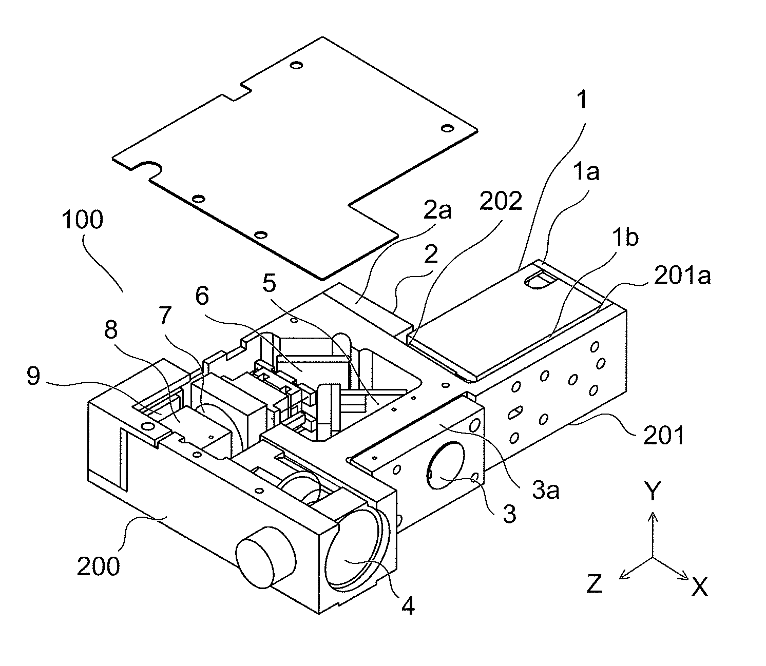
[0030]First, the configuration of an image display apparatus main body will be explained with reference to FIG. 1. FIG. 1 is a schematic perspective view of the image display apparatus main body according to the embodiment 1 of the present invention.

[0031]In FIG. 1, the image display apparatus main body 100 uses laser light as a light source and performs magnification and projection on the screen (not shown in the drawing). The image display apparatus main body 100 has three light sources, that is, a green color laser light source apparatus 1 (first laser light source), a red color laser light source apparatus 2 ...

embodiment 2

[0072]Embodiment 2 of the present invention be hereinafter described with reference to FIGS. 8 to 12. Component members having the same configuration and function as the embodiment 1 will be given the same numerical references and the detailed illustration thereof will be omitted.

[0073]The arranged location and shape of the fin 34, and the location of air inlet ports in the embodiment 2 are different from the embodiment 1. The differences are described hereafter in detail.

[0074]FIG. 8 is an exploded view of an image display apparatus according to the embodiment 2 of the present invention. As shown in FIG. 8, the tilted portion 30 houses the image display apparatus main body 100 that has been described with reference to FIG. 1, the cooling fan 23, the fin 34, and the like. A bottom portion 34c of the fin 34 is arranged directly above air inlet ports 22a (in a vertical direction of the air inlet ports 22a). The cooling fan 23 is arranged directly above the bottom portion 34c of the fi...


PUM


Abstract

An image display apparatus of the present invention includes an air passage formed by connecting an air inlet port and an exhaust port inside a case having the air inlet port and the exhaust port, and an air blower that is arranged in the air passage. At least a part of a heat dissipator of a red color laser light source apparatus having the lowest upper limit of an operating temperature is arranged in the air passage closer to the air inlet port than heat dissipators of other laser light sources and also directly below the cooling fan. Hence, it is possible to provide the image display apparatus that inhibits image quality deterioration.

Description

CROSS-REFERENCE TO RELATED APPLICATIONS[0001]The present application claims priority under 35 U.S.C. §119 of Japanese Application No. 2010-263359, filed on Nov. 26, 2010, the disclosure of which is expressly incorporated by reference herein in its entirety.BACKGROUND OF THE INVENTION[0002]1. Field of the Invention[0003]The present invention relates to an image display apparatus in which a laser light source apparatus using a semiconductor laser is incorporated.[0004]2. Description of Related Art[0005]In recent years, laser light has drawn attention as a light source of an image display apparatus which can perform large-screen display, and technology development of a semiconductor laser has been promoted to form this laser light. Compared with an ultra-high pressure mercury lamp (UHP lamp) conventionally used as a light source of an image display apparatus or a light-emitting diode (LED) recently used in a small-sized image display apparatus, a light source using a semiconductor lase...

Claims


Application Information

Patent Timeline
Patent Type & Authority Applications(United States)
IPC IPC(8): F21V9/00F21V29/02
CPCG03B21/16H04N9/3161H04N9/3144G03B21/2033
Inventor ENOMOTO, HIROFUMITESHIMA, YOSHIHIROSUYAMA, KOHEI
Owner PANASONIC CORP
Why Eureka
Try Eureka