Active retinal implant

Active Publication Date: 2012-05-24
UNIV TUBINGEN
View PDF1 Cites 9 Cited by
  • Summary
  • Abstract
  • Description
  • Claims
  • Application Information

AI Technical Summary

Benefits of technology

[0038]In view of the above, the object underlying the present invention is to provide a retinal implant which takes into account these observations and which avoids or reduces disadvantages from the prior art.
[0099]In this case, it is advantageous that directly neighbouring cell populations, which were modified by rhodopsin with different spectral sensitivities, can be actuated separately and this increases the resolution and / or the contrast of the seen image.

Problems solved by technology

A further problem in the known retinal implants is the energy supply of the stimulation chip.
That is to say, the energy for generating the electrical stimulation signals cannot be obtained from the incident useful light itself, even in subretinal implants, and so additional external energy is required.
However, since wireless retinal implants for human applications that have a satisfactory quality are not currently available, at the moment use is made of not only epiretinal but also subretinal implants, which are supplied with the required external energy by wires.
That is to say that, in the case of AC voltage supply, the rectifiers required on the implant would need too much space and also could not be implemented in integrated circuits in a technically expedient fashion, in particular due to the required smoothing capacitors.
However, in the long run, the wired transmission of DC voltage leads to electrolytic decomposition processes in the tissue surrounding the wire and so this method of supplying implants with external energy is also unsatisfactory.
Despite the above-described promising approaches for solving the substantial technological problems in the context of epiretinal and, in particular, subretinal retinal implants, the currently available retinal implants do not yet satisfy possibly all requirements for comprehensive and satisfactory patient care.
Even if it seems possible to increase the light sensitivity of rhodopsin-controlled channels by up to three orders of magnitude, the sensitivity of the rods and cones will not be achievable under any circumstances, not even approximately, because the other cells of the retina, which are made light sensitive by rhodopsin, lack the particular amplifying mechanisms of the rods and cones.

Method used


Image

  • Active retinal implant
  • Active retinal implant
  • Active retinal implant

Examples


Embodiment Construction

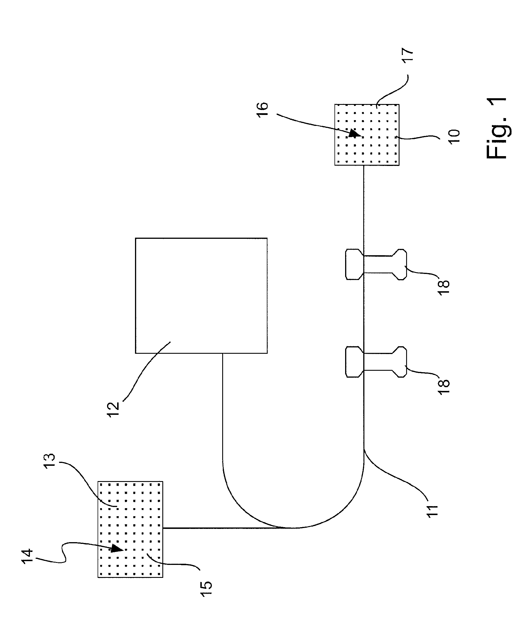
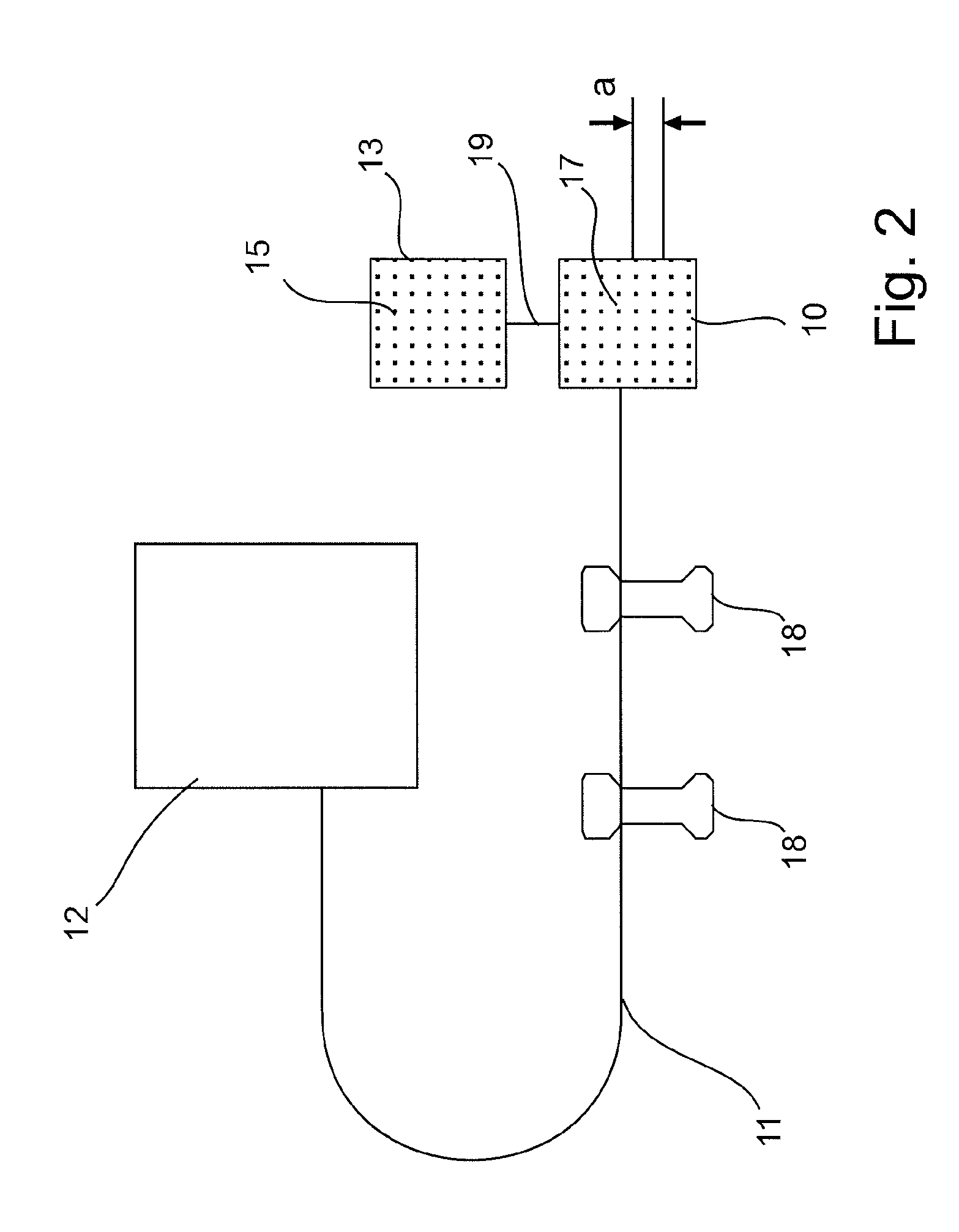
[0129]FIG. 1 schematically illustrates a first embodiment of an active retinal implant 10, in which the dimensions have not been reproduced to scale.

[0130]A wire 11 is used to connect the retinal implant 10 to a supply unit 12 and an image receiver 13, with an array 14 of image cells 15 being arranged thereon and being designed, for example, as photodiodes. An array 16 of radiation-emitting stimulation elements 17 is arranged on the retinal implant 10 in order to output optical stimulation signals. By way of example, the stimulation elements 17 are designed as light-emitting diodes (LEDs).

[0131]The supply unit 12 supplies the retinal implant 10 with electrical energy and possibly with control signals, which can be used to influence or set different functions of the retinal implant.

[0132]The image receiver 13 uses the image cells 14 thereof for converting incident ambient light into spatially resolved electrical signals that are guided to the retinal implant 10 and are, at said locat...


PUM


Abstract

An active retinal implant (10) to be implanted into an eye has an array (16) of stimulation elements (17) that emit stimulation signals to cells of the retina, wherein the stimulation elements (17) are designed as radiation-emitting elements.

Description

[0001]This is a continuation application of copending international patent application PCT / EP 2010 / 001126, filed Feb. 24, 2010 and designating the United States, which was published in English as WO 2010 / 105728 A2, and claims priority to German patent application DE 10 2009 015 389.6, filed Mar. 20, 2009. The content of these prior applications are incorporated herein by reference in their entirety.BACKGROUND OF THE INVENTION[0002]1. Field of the Invention[0003]The present invention relates to an active retinal implant to be implanted into an eye, with an array of stimulation elements that emit stimulation signals to cells of the retina.[0004]2. Related Prior Art[0005]By way of example, such a retinal implant has been disclosed in WO 2005 / 000395 A1.[0006]The known retinal implant serves to counteract a loss of vision due to degenerations of the retina. Here, the basic idea is to implant into the eye of a patient a microelectronic stimulation chip that replaces the lost vision by ele...

Claims


Application Information

Patent Timeline
IPC IPC(8): A61F9/08A61M37/00C12M1/42A61N1/36
CPCA61N1/36046A61N1/0543
Inventor WROBEL, WALTER G.ZRENNER, EBERHARTROTHERMEL, ALBRECHT
Owner UNIV TUBINGEN
Why Eureka
Try Eureka