Transflective LCD device

a technology of lcd and transparent film, applied in non-linear optics, instruments, optics, etc., can solve the problems of insufficient reflective brightness, large amount of power supply, device, etc., and achieve the effect of reducing the uneven area of the insulating layer, reducing light leakage areas, and increasing image contras

Active Publication Date: 2011-10-06
AU OPTRONICS CORP
View PDF4 Cites 2 Cited by
  • Summary
  • Abstract
  • Description
  • Claims
  • Application Information

AI Technical Summary

Benefits of technology

[0015]The object the present invention is to provide a transflective LCD device, in which, dark-state light leak problem is eliminated so as to enhance the image contrast as well as the aperture ratio.
[0021]As far as the aperture ratio is concerned, the transflective LCD panel of the present invention has high aperture ratio since one light leakage area is reduced in each of the sub-pixel regions. In addition, since only one light leakage area is remained on the inclined sides of the insulating layer, the unbalance alignment of the crystal molecules due to turning when current passed through is consequently reduced, thereby achieving the desired alignment of the crystal molecules.
[0023]Due to the present design, the reflective and transmissive areas of two adjacent sub-pixel regions are juxtaposed to each other, thereby reducing the uneven area of the insulating layer. Thus, the alignment of the crystal molecules within the LCD layer is not disturbed due to the reduction of the uneven area in the insulating layer, but results in lesser light leakage areas, which, in turn, increases the image contrast of the transflective LCD panel of the present invention.

Problems solved by technology

A backlight module is used in the transmissive LCD device and consumes a great amount of power source.
Under the high ambient light (i.e. sunlight), the device has poor display ability.
Therefore, no backlight module is utilized in the reflective LCD device, but the latter suffers from non-uniform reflective brightness, thereby causing insufficient of the reflective brightness and cannot be operated under the dark environment.
This conventional transflective LCD works similar to the previous structure, and has the light leakage problem.

Method used


Image

  • Transflective LCD device
  • Transflective LCD device
  • Transflective LCD device

Examples


Embodiment Construction

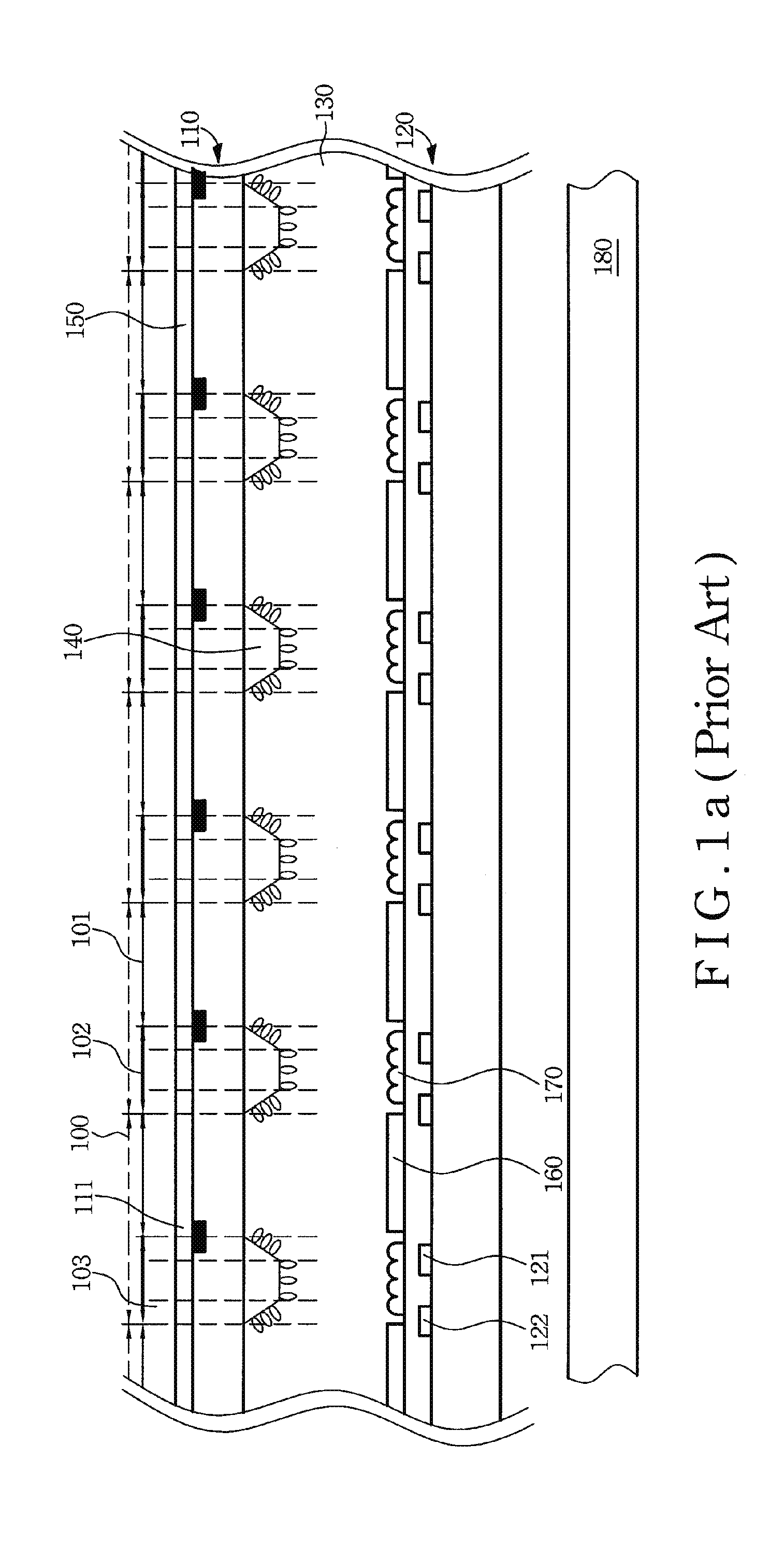
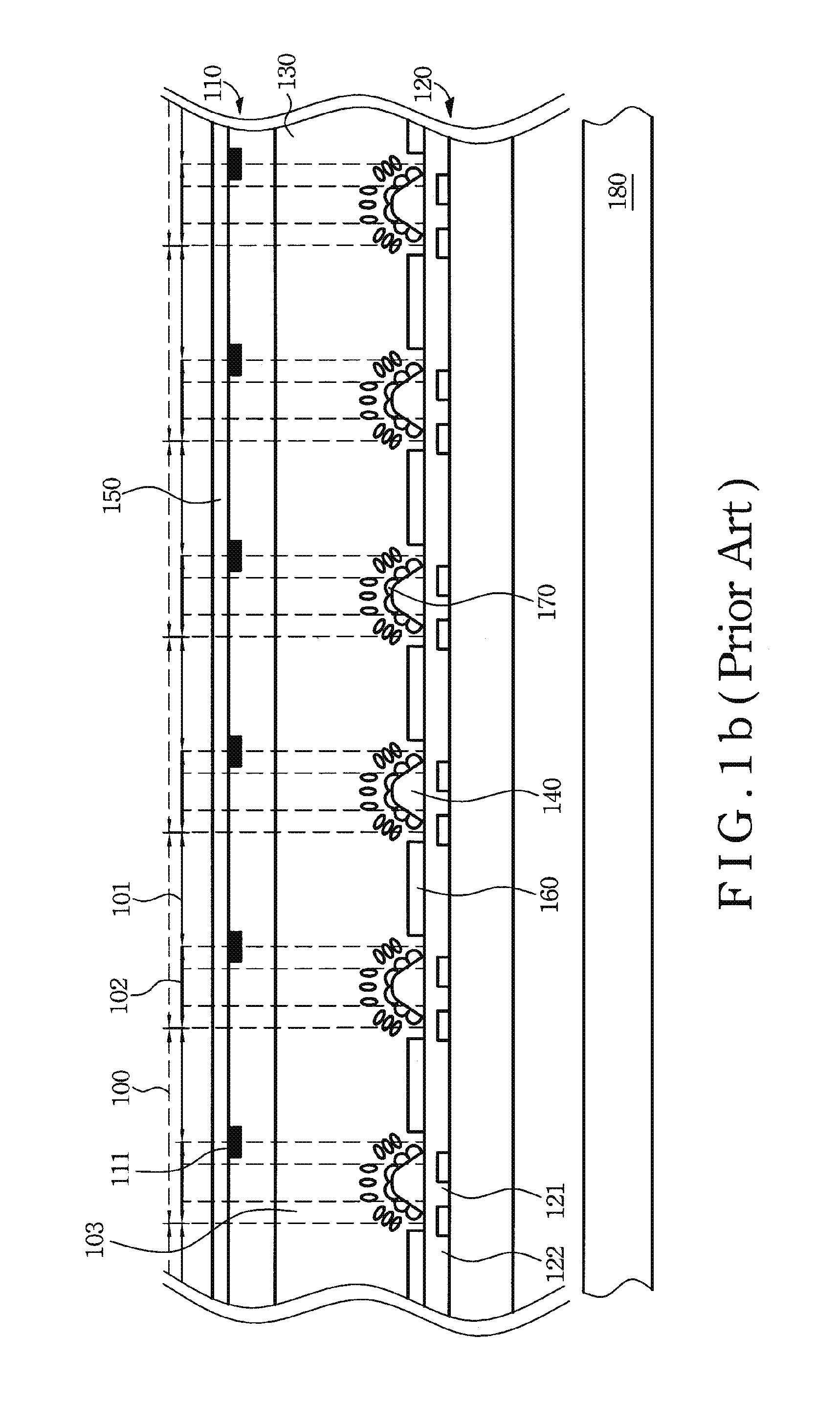
[0035]A transflective LCD device of the present invention is constructed in order to improve the dark-state light leakage problem encountered in the conventional transflective LCD device so as to raise the aperture ratio thereof.

[0036]The transflective LCD device of the present invention includes an array substrate, a color filter and a liquid crystal display layer. In addition, an insulating layer is disposed either on the color filter or the array substrate. Depending on formation of the insulating layer, the transflective LCD device of the present invention can be classified into two types.

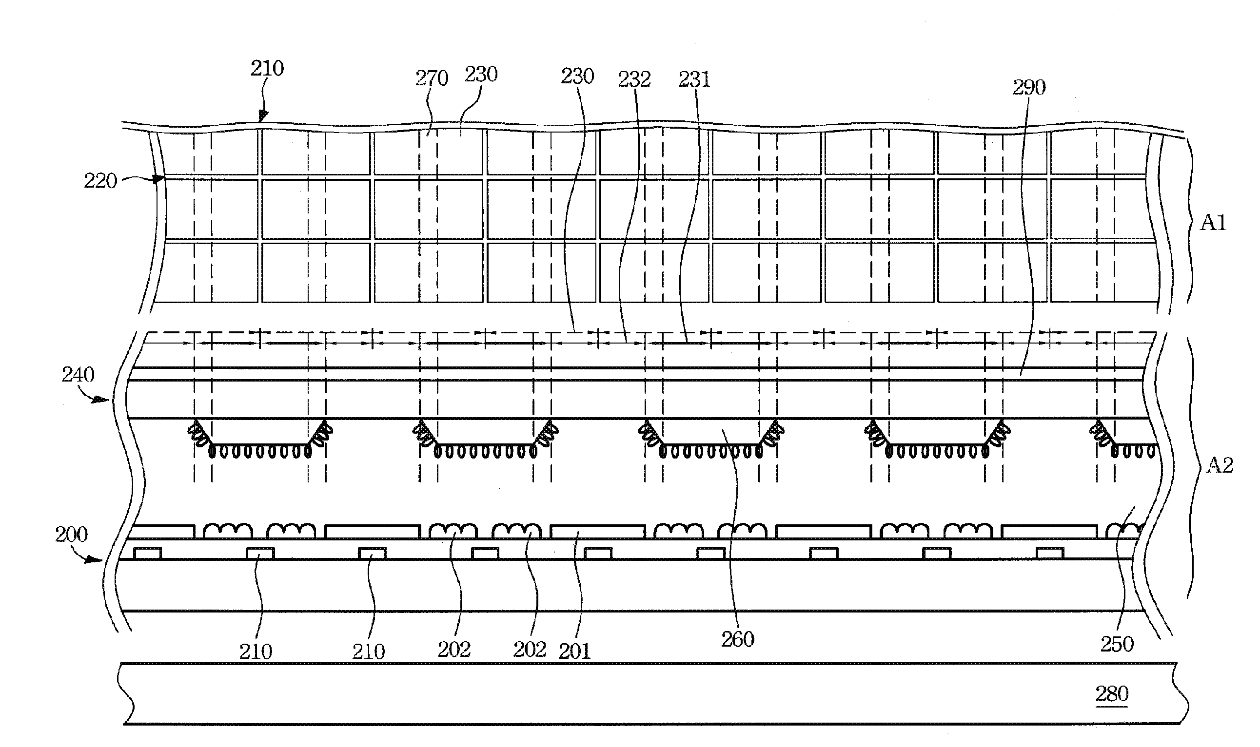
[0037]FIG. 2a shows a first type transflective LCD device of the present invention, in which, the insulating layer 260 is disposed on the color filter 240. The array substrate 200 accordingly includes a plurality gate lines 210, a plurality of common lines (not shown) substantially parallel to the gate lines, and a plurality of data lines 220.

[0038]Referring FIG. 2a, a top view A1 is shown, whe...


PUM

PropertyMeasurementUnit
sunlightaaaaaaaaaa
reflective brightnessaaaaaaaaaa
transmissive areaaaaaaaaaaa

Abstract

A transflective LCD device includes an array substrate and a color filter. The substrate includes a plurality gate lines, a plurality of common lines, and a plurality of data lines substantially crossing the gate lines to define a plurality of sub-pixel regions. Each sub-pixel region has a reflective area and a transmissive area. Two of the reflective area of two adjacent sub-pixel regions in the same column are juxtaposed to each other. The color filter has a plurality of sub-pixel regions respectively aligned with the sub-pixel regions of the array substrate. The color filter includes an insulating layer disposed on the reflective area of a respective sub-pixel region. An LC layer is disposed between the array substrate and the color filter.

Description

CROSS-REFERENCE TO RELATED APPLICATIONS[0001]This application is a Divisional of prior pending application Ser. No. 12 / 181,620 filed on Jul. 29, 2008, which claims priority to Taiwan Patent Application No. 96131920 filed on Aug. 28, 2007. All of which are hereby expressly incorporated by reference into the present application in their entirety. The present invention relates to an LCD (liquid crystal display) device, and more specifically to a transflective LCD device.BACKGROUND OF THE INVENTIONDescription of the Prior Art[0002]Due to development in the technology, multi-media products, such as mobile phones, notebook computers, digital cameras, PDAs and display screens, become more common and the demand for LCD (liquid crystal display) device is increasing day-by-day.[0003]The LCD device can be generally classified into three types, namely: (1) transmissive (2) reflective and (3) transflective depending on supply of the light source. A backlight module is used in the transmissive LC...

Claims


Application Information

Patent Timeline
Patent Type & Authority Applications(United States)
IPC IPC(8): G02F1/1335
CPCG02F1/133514G02F1/133707G02F1/133555
Inventor CHENG, CHING-SHENGLIU, LI-PINGFAN JIANG, SHIH-CHYUANPEI, CHIH-CHUNHU, CHIH-JENLIN, CHING-HUANCHANG, CHIH-MING
Owner AU OPTRONICS CORP
Why Eureka
Try Eureka