
Apparatus and system for improving depth of focus

a technology of optical apparatus and depth of focus, applied in the field of optical apparatus and system, can solve the problems of reducing machining quality and over-extending the range of dof, and achieve the effects of improving depth of focus, improving quality and efficiency of optical processing, and increasing the dof for optical processing

Active Publication Date: 2012-05-24
IND TECH RES INST
View PDF4 Cites 6 Cited by
  • Summary
  • Abstract
  • Description
  • Claims
  • Application Information

AI Technical Summary

Benefits of technology

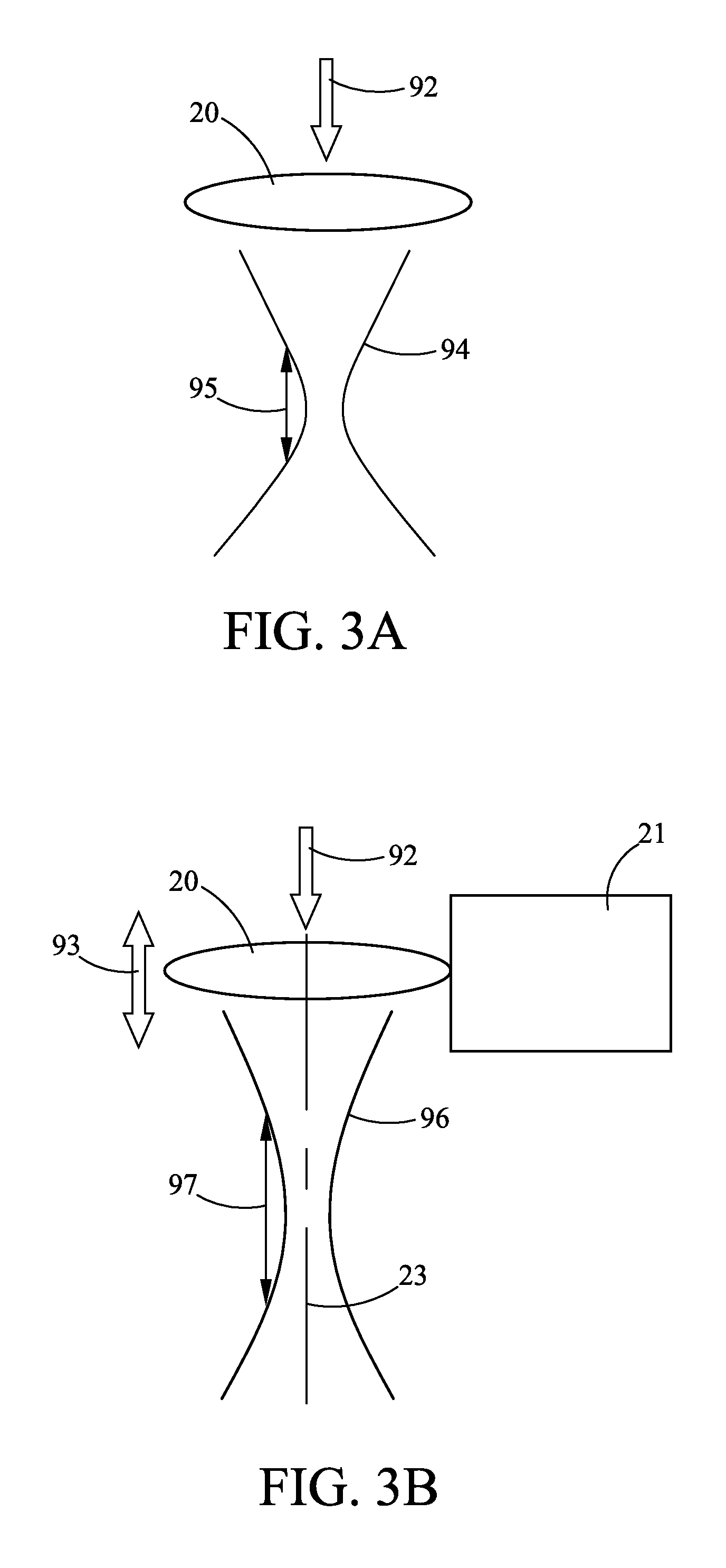
[0004]The present disclosure provides an optical apparatus and system for improving depth of focus (DOF), capable of enabling an actuator to vibrate while transmitting the vibration to an optical lens module coupled to the actuator for causing a vibration to be caused on the optical axis of the optical lens module, and thus increasing the DOF for an optical processing. Thereby, problems associated with working out of focus under the restriction of a very small DOF can be prevented, and the quality and efficiency of the optical processing can be enhanced.
[0005]The present disclosure further provides an optical apparatus and system for improving depth of focus (DOF), capable of enabling an actuator to vibrate while transmitting the vibration to an optical lens module coupled to the actuator, and thereby, with the design of the optical lens module that is configured with converging lenses and diverging lenses, the vibrating amplitude on the optical axis of the optical lens module is amplified for enabling the DOF for an optical process to be increased by factors, and thus causing the quality and efficiency of the optical processing to be enhanced.
[0007]In another embodiment, the present disclosure provides an optical system for improving depth of focus (DOF), comprising: a light source, for emitting a beam to be used in a machining process; an optical lens module; for focusing the beam; and an actuator, coupled to the optical lens module; wherein, the actuator is actuated by a driving signal for issuing a vibration frequency to the optical lens module for controlling the same to vibrate in a specific vibration frequency on the optical axis of the optical lens module, causing the focus position of the beam to varying accordingly, and thus, causing the DOF of the optical system to increase.

Problems solved by technology

Nevertheless, in a laser machining process performed under the restriction of a very small DOF, any careless operation for moving a mobile component in the laser machining platform or even a slight deflect to the flatness of the film to be machined can cause the machining to excess the range of the DOF, causing the machining quality to drop significantly.

Method used


Image

  • Apparatus and system for improving depth of focus
  • Apparatus and system for improving depth of focus
  • Apparatus and system for improving depth of focus

Examples


Embodiment Construction

[0019]For your esteemed members of reviewing committee to further understand and recognize the fulfilled functions and structural characteristics of the disclosure, several exemplary embodiments cooperating with detailed description are presented as the follows.

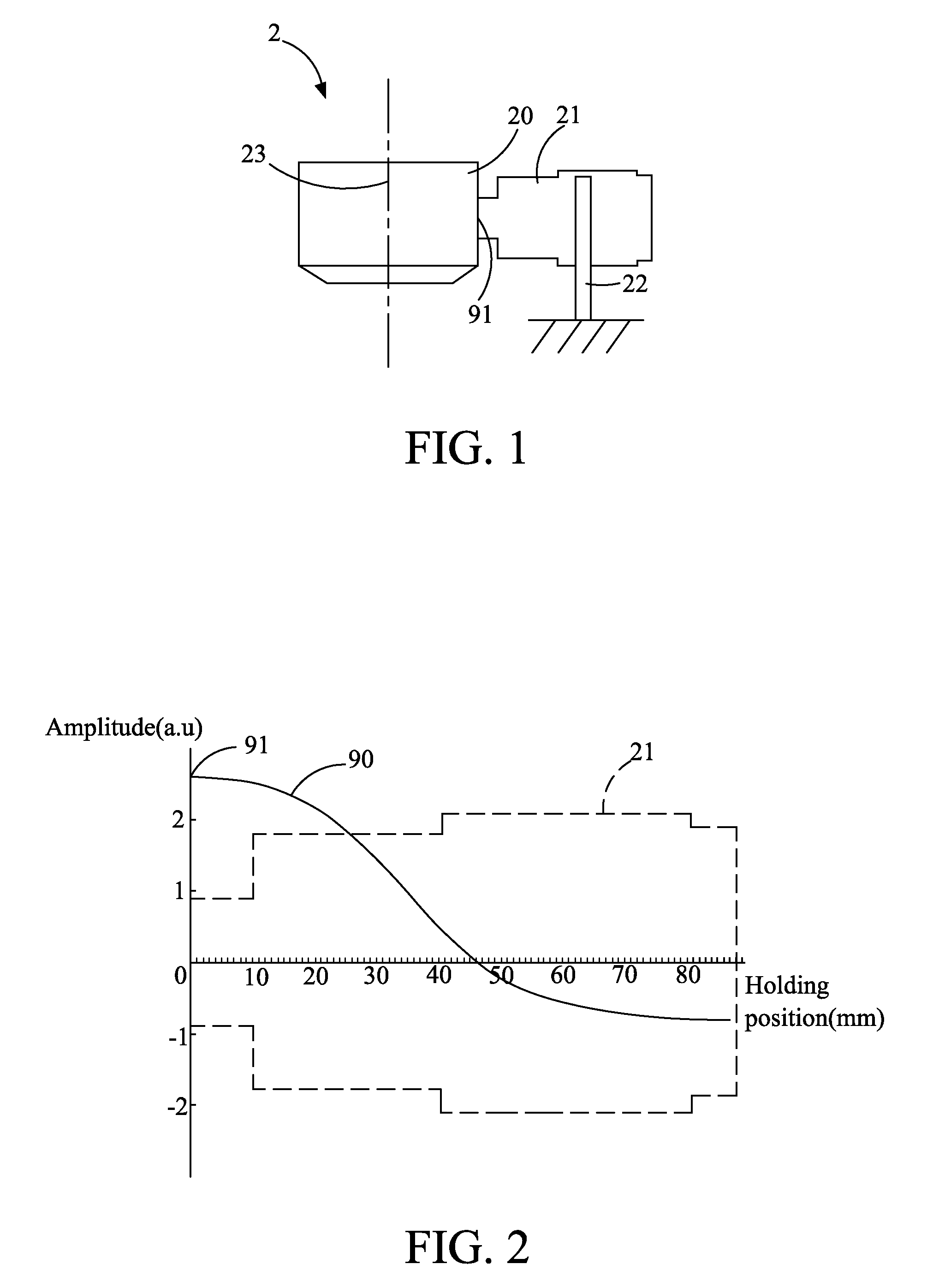
[0020]Please refer to FIG. 1 is a schematic diagram showing an optical apparatus for improving DOF according to an embodiment of the present disclosure. In this embodiment, the optical apparatus 2 is composed of: an optical lens module 21 and an actuator 21 in a manner that the actuator 22 is coupled to the optical lens module 20 and can be a piezoelectric vibrator, but is not limited thereby. Moreover, the optical lens module is configured with a holding device 22 for holding the actuator 21. Thereby, the actuator 21 can be is actuated by a driving signal for issuing a vibration frequency to the optical lens module 20 for controlling the same to vibrate on the optical axis 23 of the optical lens module 20, and consequently, ...


PUM

PropertyMeasurementUnit
vibration frequencyaaaaaaaaaa
wavelengthaaaaaaaaaa

Abstract

The present invention provides an apparatus and a system for improving depth of focus (DOF), wherein an optical lens for optical processing is actuated to vibrate whereby the DOF of the optical processing is increased due to the variation of focal point. In the embodiment of the present invention, an actuator is coupled to the optical lens for providing vibration energy wherein the optical lens is actuated by the vibration energy so as to vibrate on an optical axis thereof so as to increase the DOF during the optical processing, thereby improving the quality and efficiency of optical processing.

Description

TECHNICAL FIELD[0001]The present disclosure relates to an optical apparatus and system, and more particularly, to an optical apparatus and system for improving depth of focus.TECHNICAL BACKGROUND[0002]Clearly, the depth of focus (DOF) and spot size of a laser machining process is determined by the focal length of its optical module, the wavelength of the laser beam, input beam size, and so on. Since the DOF of an optical device for a laser machining process is usually proportional to the spot size of the laser machining process, i.e. when a high precision laser machining is performed using a small spot size, the DOF of the optical module for the laser machining is usually very small. Nevertheless, in a laser machining process performed under the restriction of a very small DOF, any careless operation for moving a mobile component in the laser machining platform or even a slight deflect to the flatness of the film to be machined can cause the machining to excess the range of the DOF,...

Claims


Application Information

Patent Timeline
Patent Type & Authority Applications(United States)
IPC IPC(8): B23K26/00G02B9/10G02B7/02
CPCB23K26/046B23K26/0648G02B27/0075B23K26/0861B23K26/0823
Inventor CHEN, CHUN-MINGLIU, SUNG-HOTSENG, JIE-TINGLEE, MIN-KAIYANG, YING-HUI
Owner IND TECH RES INST
Learn More