
Spectrum measuring apparatus for mover

a spectrum measurement and moving body technology, applied in the direction of optical radiation measurement, instruments, spectrometry/spectrophotometry/monochromators, etc., can solve the problems of difficulty in correctly recognizing the existence of a pedestrian on the basis of the shape obtained, and the above-mentioned image processing has its limits, so as to achieve reliable acquisition of discrimination information

Inactive Publication Date: 2012-05-17
TOYOTA JIDOSHA KK
View PDF6 Cites 28 Cited by
  • Summary
  • Abstract
  • Description
  • Claims
  • Application Information

AI Technical Summary

Benefits of technology

[0008]Accordingly, it is an objective of the present invention to provide a movable body spectrum measuring apparatus that reduces the influence of ambient light on data captured by the spectrum sensor mounted on a movable body such as a vehicle, thereby enabling discrimination of a measuring object with higher reliability.Means for Solving the Problems
[0062]The present invention with the above-mentioned configuration is especially effective for the automobile as the movable body provided with the spectrum sensor, and enables very reliable acquisition of discrimination information of the measuring object, which is necessary for supporting driving of the automobile.

Problems solved by technology

However, since the shape of a pedestrian generally varies depending on size, orientation or presence or absence of his / her belongings, it is difficult to correctly recognize the existence of a pedestrian on the basis of the shape obtained by the above-mentioned image processing.
Although traffic lights are highly standardized in size and color, the shapes disadvantageously vary depending on the viewing angle, and shape recognition through the above-mentioned image processing has its limits.

Method used


Image

  • Spectrum measuring apparatus for mover
  • Spectrum measuring apparatus for mover
  • Spectrum measuring apparatus for mover

Examples


first embodiment

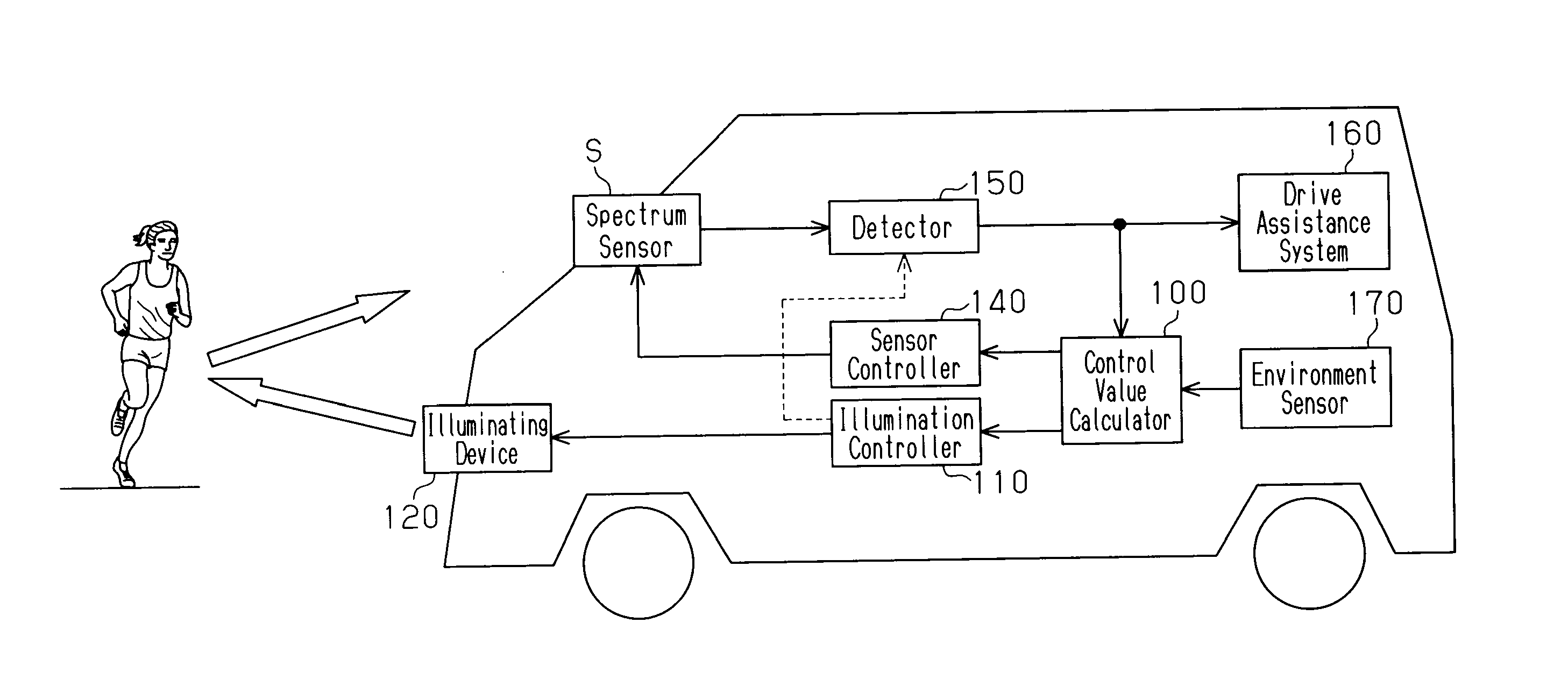
[0113]FIG. 1 shows a schematic configuration of a movable body spectrum measuring apparatus according to a first embodiment of the present invention.

[0114]As shown in FIG. 1(a), the movable body spectrum measuring apparatus includes a control value calculator 100 that, in monitoring of a measuring object such as a pedestrian, a traffic light or an obstacle through a spectrum sensor S mounted on a vehicle such as an automobile, controls a radiation mode of reference light radiated toward the measuring object or an imaging spectral characteristic of the spectrum sensor S itself to calculate a control value for varying feature value of a wavelength range and light intensity at each wavelength of observation light, which is detected by the spectrum sensor S. The control value calculator 100 has a control value map as shown in FIG. 1(b), an illumination controller 110 controls illumination of an illumination device 120 on the basis of the control value map, and a sensor controller 140 co...

second embodiment

[0134]A movable body spectrum measuring apparatus according to a second embodiment of the present invention will be described below with reference to FIGS. 12 to 14. In the second embodiment, the light source of the illumination device is the halogen lamp and its basic configuration of this embodiment is common to that of the first embodiment.

[0135]That is, as shown in FIG. 12, an illumination device 120A adopted in this embodiment is configured of a halogen lamp 121 and an optical filter varying plate 122 that covers a surface of the halogen lamp 121. As shown in FIG. 13, the optical filter varying plate 122 is configured of a plurality of optical filters 122A to 122H having different wavelength characteristics and transmittances. The wavelength range and the light intensity at each wavelength of the reference light radiated from the illumination device 120 are changed through selection among the optical filters 122A to 122H. As shown in FIG. 14(a), transmittances Ta to Tc of the o...

third embodiment

[0139]A movable body spectrum measuring apparatus according to a third embodiment of the present invention will be described below with reference to FIGS. 15 and 16. In the third embodiment, like the second embodiment, the light source of the illumination device is the halogen lamp and its basic configuration is common to that of the first embodiment. In the third embodiment, the wavelength range and the light intensity at each wavelength of the reference light radiated from the illumination device are adjusted by light interference.

[0140]That is, an illumination device 120B adopted in this embodiment includes, as shown in FIG. 15, a spectroscope 123 such as a prism that separates light radiated from the halogen lamp 121 according to wavelength. The light separated by the spectroscope 123 is diffracted by phase plates 124 provided corresponding to the light wavelength. At this time, the phase of each of the separated light wavelengths is adjusted by inclination of the phase plates 1...


PUM


Abstract

Disclosed is a mover spectrum measuring apparatus, which is able to discriminate an object being measured more reliably by relieving the influences of an environmental light on photographic data by a spectrum sensor mounted on a mover such as a vehicle. A spectrum sensor capable of measuring wavelength information and optical intensity information is mounted on a vehicle, so that an object being measured around the vehicle is discriminated on the basis of the spectrum data relating to the observation light detected by the spectrum sensor. The mover spectrum measuring apparatus comprises an illumination device for making variable the featuring quantity of at least either the wavelength range of the observation light or the optical intensity of each wavelength, and controls the featuring quantity varying mode by the illumination device through an illumination controller on the basis of the control value according to an environmental element.

Description

TECHNICAL FIELD[0001]The present invention relates to a movable body spectrum measuring apparatus for discriminating a measuring object on the basis of spectrum data regarding the measuring object as measured by a spectrum sensor mounted on a movable body such as a vehicle, in particular, an automobile.BACKGROUND ART[0002]In recent years, vehicles such as automobiles have been often provided with a drive assisting device that recognizes the state of a pedestrian, a traffic light or the like, which dynamically varies around the vehicle, and assists driving and decision making for the driver. Most of such apparatuses take an image of the state of a traffic light, a pedestrian or the like by use of a CCD camera, processes the taken image in real time to recognize the state and uses the recognition result for the above-mentioned assistance for driving. However, since the shape of a pedestrian generally varies depending on size, orientation or presence or absence of his / her belongings, i...

Claims


Application Information

Patent Timeline
IPC IPC(8): G06F7/00G01J3/28
CPCG01J3/02G01J3/0208G01J3/021G01J3/0235G01J2003/1213G01J3/36G01J5/0025G01J2003/104G01J3/10
Inventor FUNAYAMA, RYUJIKAWAMATA, SHINYAENDO, MASATOYOKOCHI, YASUKATAYOSHIDA, YASUHIROKITAHAMA, KENICHI
Owner TOYOTA JIDOSHA KK
Learn More