
Weak signal acquisition

a weak signal and receiver technology, applied in the field of pseudonym noise receivers, can solve problems such as loss of valuable data transmitted from satellites, and achieve the effect of increasing the efficiency of the receiver

Active Publication Date: 2007-04-19
ACCORD SOFTWARE & SYST PVT
View PDF7 Cites 19 Cited by
  • Summary
  • Abstract
  • Description
  • Claims
  • Application Information

AI Technical Summary

Benefits of technology

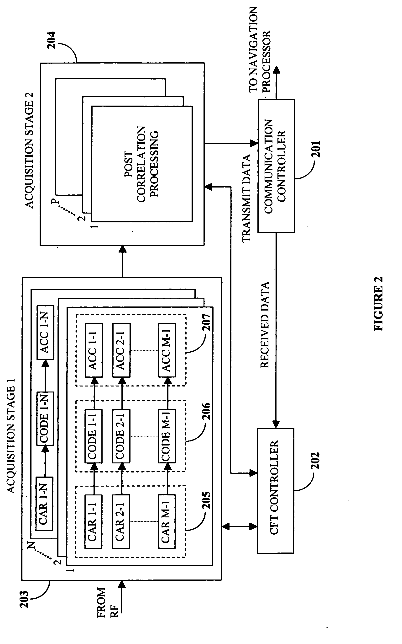
[0004] The proposed invention provides a method and an apparatus to detect a weak pseudorandom noise (PRN) signal in the presence of a strong PRN signal, where the weak signal is partially masked by the strong signal in a PRN receiver. The proposed invention uses a special chip-frequency-time multiplexed (CFT) correlator for identification of the auto-correlation peak due to the weak satellite signal from the cross-correlation peaks due to the strong satellite signal by employing two techniques, namely the millisecond boundary correlation histogram method, and the frequency response correlation histogram method. The two methods can be used independently or in parallel to increase the efficiency of the receiver, so that even if one method fails, the other method yields the desired results.
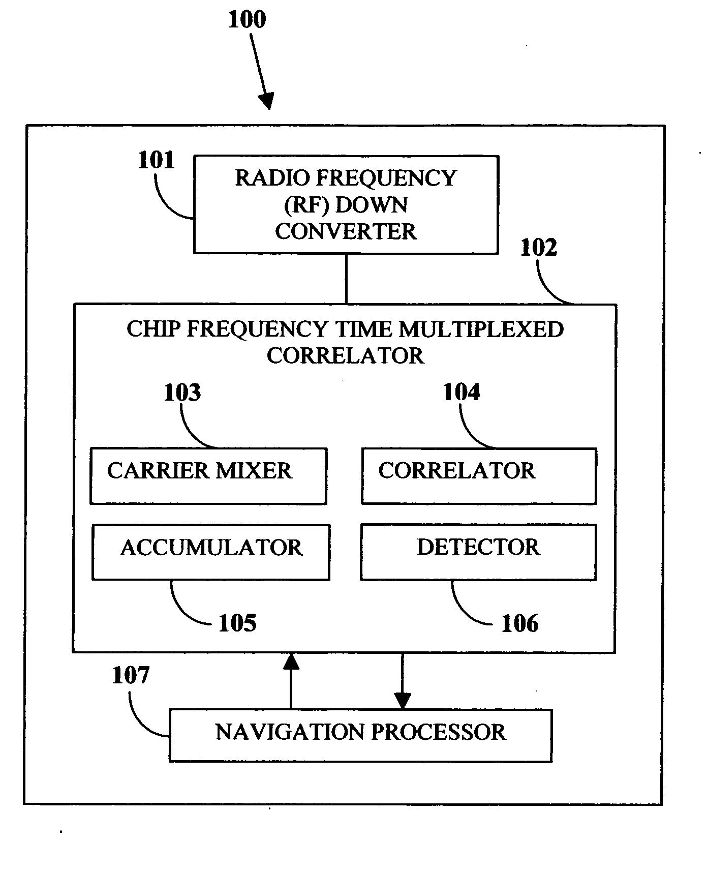
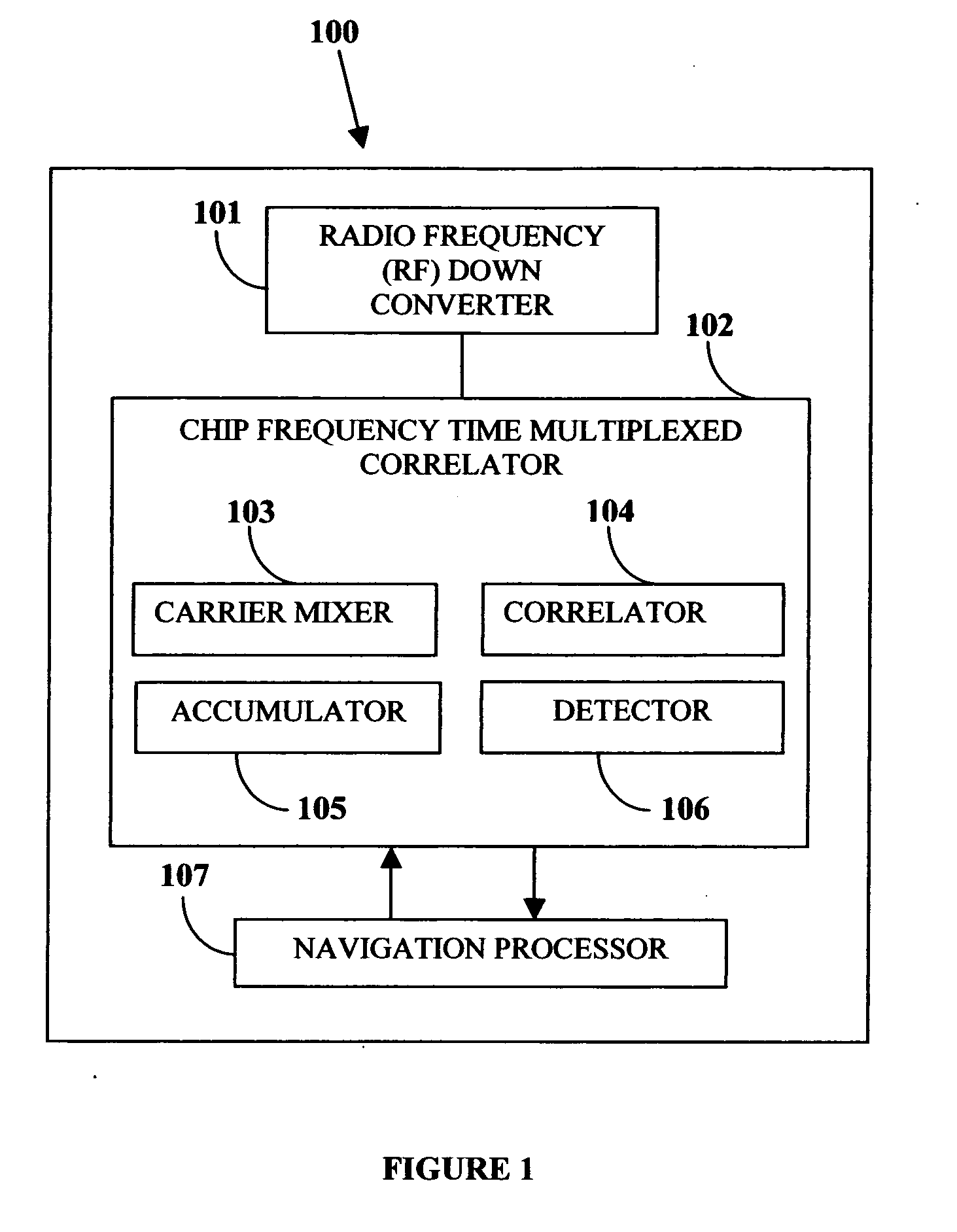
[0005] The proposed invention uses an apparatus that employs the above-mentioned techniques for weak signal acquisition is a PRN ranging GPS receiver. The PRN ranging receiver consists of a radio frequency (RF) front end, a chip-frequency-time multiplexed (CFT) correlator and individually programmable large correlator and an embedded processor. The CFT correlator provides multiple correlation peaks within the code chip delay search range, and also allows an increase in the signal integration period dynamically, thereby enabling weak signal detection using the aforesaid techniques. This architecture of the GPS receiver is suitable for a variety of applications including E-911 and car navigation, for reliable signal acquisition in indoor and other constrained environments.
[0008] This invention allows detection of a weak signal when it is partially masked by a strong signal and provides an effective solution for weak signal acquisition even when the weak and the strong signals arrive at the GPS receiver at the same Doppler frequency.
[0009] The method disclosed herein also searches for progressively weaker and weaker signals by continuous integration and peak examination, without discarding the prior data, thereby improving the search efficiency for weak signal acquisition in the GPS receiver.

Problems solved by technology

Interferences from the undesirable strong signals result in loss of valuable data transmitted from the satellite.

Method used


Image

  • Weak signal acquisition
  • Weak signal acquisition
  • Weak signal acquisition

Examples


Embodiment Construction

[0021] The method disclosed herein presents a method of acquiring a weak satellite signal in the presence of a strong interfering satellite signal at a GPS receiver, using two techniques, namely the millisecond boundary correlation histogram method and the frequency response correlation histogram method. Both the techniques distinguish between the correlation characteristics of auto-correlation and cross-correlation peaks. A chip-frequency-time multiplexed (CFT) correlator applies the millisecond boundary correlation histogram and frequency response correlation histogram methods to distinguish the auto-correlation peak from the cross-correlation peaks.

[0022]FIG. 1 illustrates the block diagram of a PRN receiver, such as a GPS receiver. The GPS receiver 100 consists of a radio frequency (RF) down converter 101 that down converts the high frequency RF signal to an intermediate frequency (IF) signal, rejects the unwanted frequency bands, and provides sufficient signal amplification. T...


PUM


Abstract

A method for acquisition of a weak signal from a satellite in the presence of a strong interfering signal from another satellite is disclosed. The method encompasses identifying the auto-correlation peak due to the weak satellite signal from the cross correlation peaks due to the strong satellite signal. This invention presents a method and apparatus of acquiring a weak satellite signal in the presence of a strong interfering satellite signal in a receiver by two techniques, namely, the millisecond boundary correlation histogram method, and the frequency response correlation histogram method. Both the techniques distinguish between the correlation characteristics for auto-correlation and cross-correlation. The apparatus presented in the invention implements the methods of weak satellite signal acquisition in presence of a strong interfering satellite signal in a pseudorandom noise (PRN) receiver.

Description

BACKGROUND OF THE INVENTION [0001] The invention disclosed herein, in general, relates to a pseudorandom noise receiver and specifically relates to a method of differentiating between an auto-correlated weak signal and a cross-correlated product of weak and strong signals in a receiver used in global positioning system (GPS). [0002] GPS satellites transmit signals to a universal receiver with a unique code called the coarse acquisition (C / A) code. The C / A code belongs to the family of gold code having a code length of 1023 chips. Signals from the satellites are coded with gold codes and transmitted at a chip rate of 1.023 MHz, with a period of 1 millisecond, with the code repeating every millisecond. Each satellite has a unique code for reception at the receiver. In correlation techniques, the incoming satellite signal is multiplied with a locally generated code. For example, the incoming satellite signal comprises a carrier of 1575.42 MHz, navigation data bits of 50 Hz and a coarse...

Claims


Application Information

Patent Timeline
IPC IPC(8): G01S5/14G01S19/21G01S19/25G01S19/24
CPCG01S19/21G01S19/24
Inventor RAY, JAYANTA KUMARCHANNARAYAPATNA, NAGARAJ SHIVARAMAIAHDESHPANDE, SAMEET MANGESH
Owner ACCORD SOFTWARE & SYST PVT
Learn More