Prismatic sealed rechargeable battery, battery module, and battery pack
a rechargeable battery and sealed technology, applied in the direction of cell components, jackets/case materials, electric devices, etc., can solve the problem of large thermal conductivity of the battery case, and achieve the effects of high power, high space efficiency per battery power, and high cooling capability
- Summary
- Abstract
- Description
- Claims
- Application Information
AI Technical Summary
Benefits of technology
Problems solved by technology
Method used
Image
Examples
embodiment 1
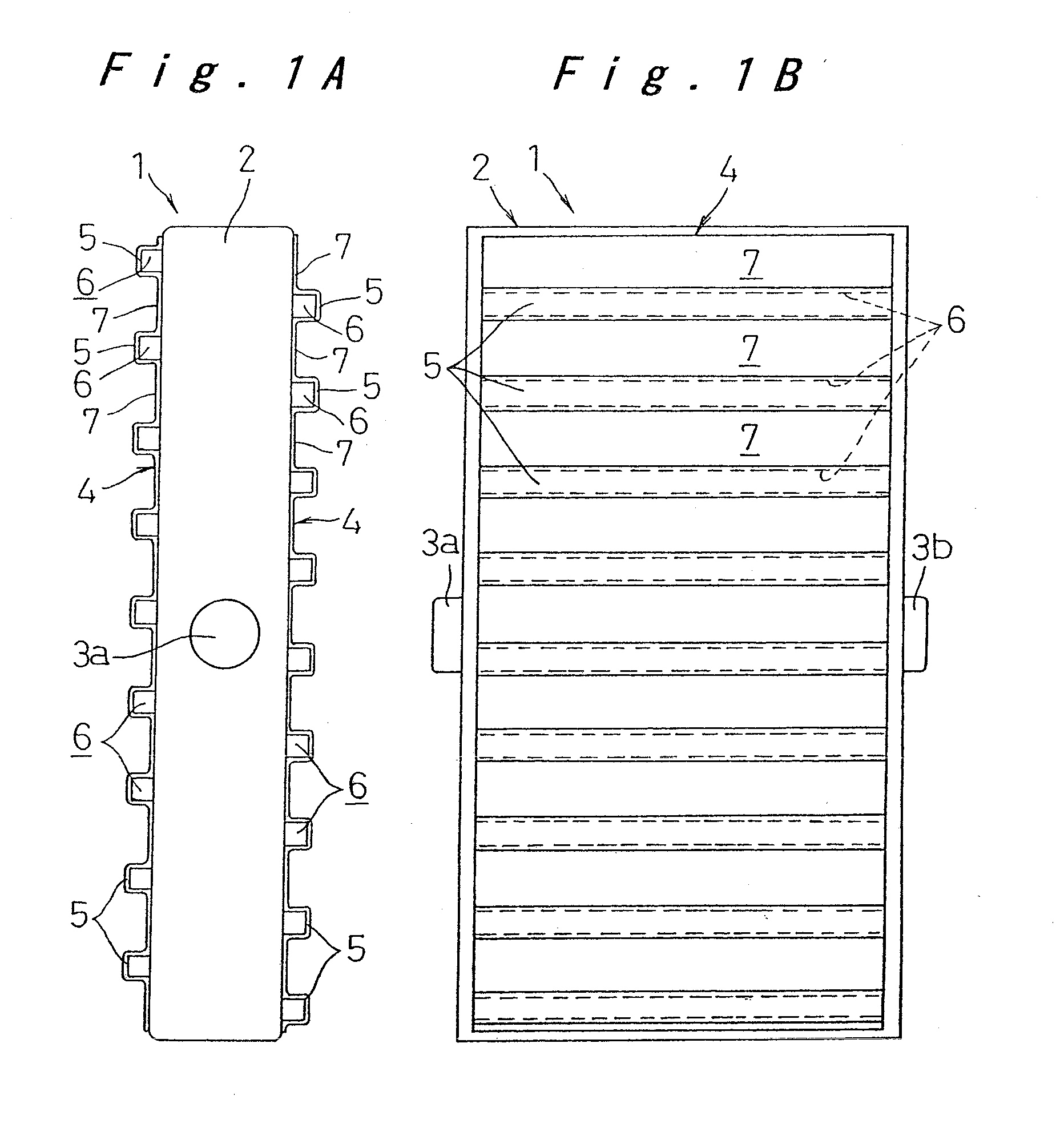
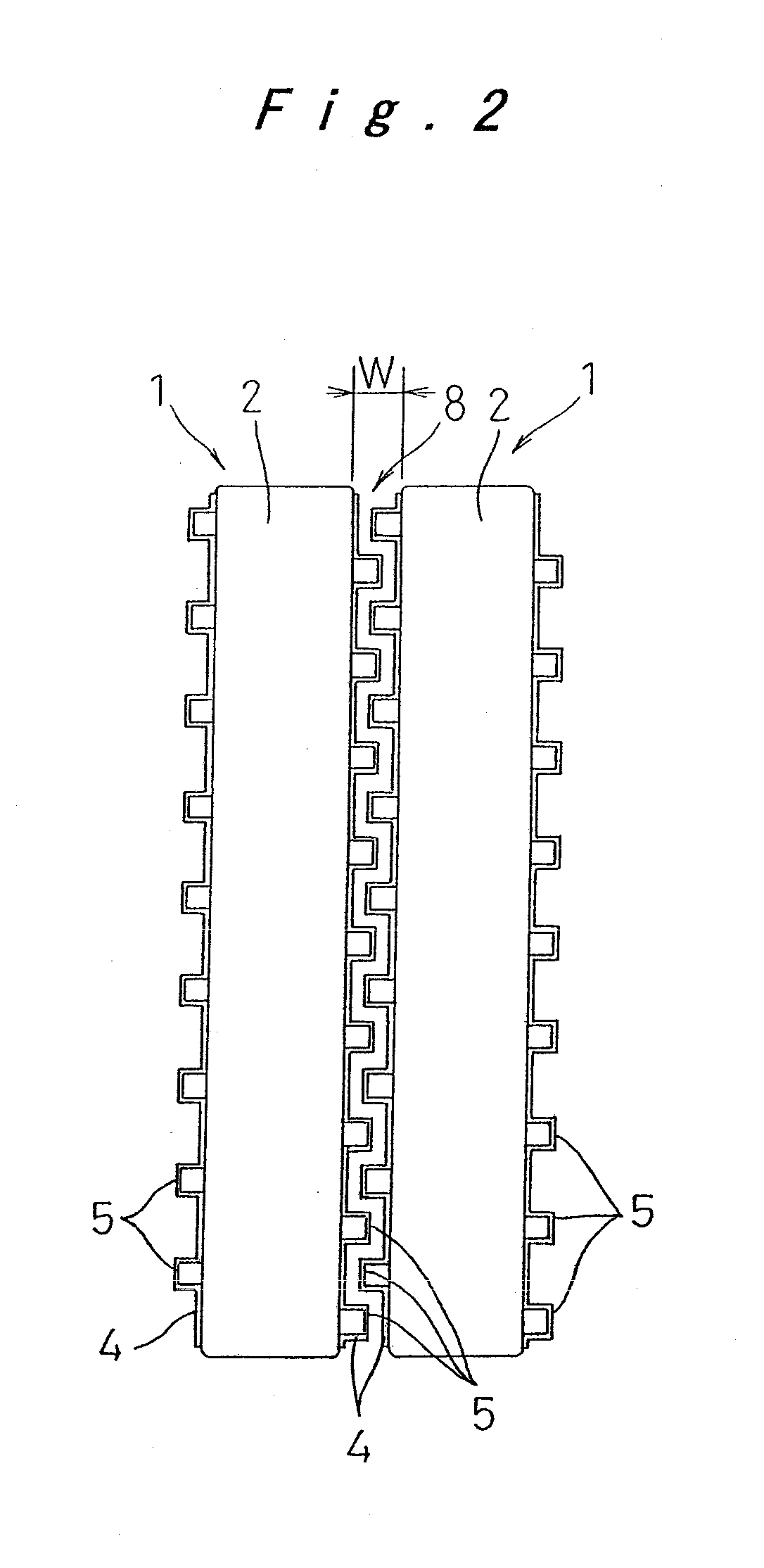
[0020]A prismatic sealed rechargeable battery and a battery module according to a first embodiment of the invention will be described below, with reference to FIGS. 1A, 1B, and 2.
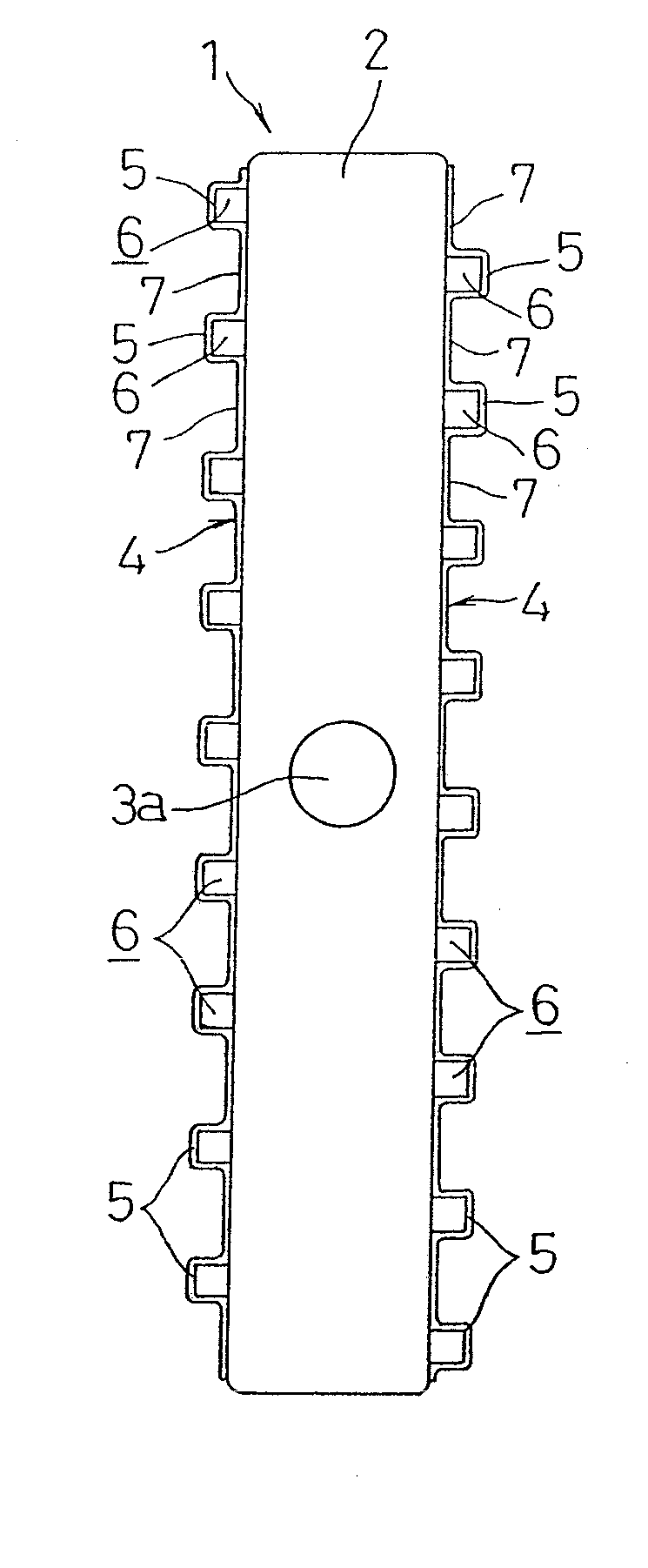
[0021]Referring to FIGS. 1A and 1B, a prismatic sealed rechargeable battery 1 includes a substantially prismatic battery case 2 formed of metal that accommodates an electrode plate assembly and an electrolyte solution. The electrode plate assembly is formed by stacking a plurality of positive electrode plates and a plurality of negative electrode plates with a separator interposed therebetween. The battery case 2 is formed by a steel plate having a thickness of about 0.3 mm to 1.0 mm that is nickel-plated in order to ensure electrolyte-resisting properties. On a pair of shorter side faces of the battery case 2 along a direction perpendicular to the longitudinal direction of the case 2, i.e., left and right side faces of the battery case 2 in FIG. 1B, a positive connection terminal 3a connected to the positi...
embodiment 2
[0033]A battery module using a prismatic sealed rechargeable battery according to a second embodiment of the invention will be described with reference to FIGS. 3A-3C.
[0034]In the present embodiment, a prismatic sealed rechargeable battery 10 constituting a battery module 11 has basically the same structure as that described in the first embodiment. Thus, the same components as those described in the first embodiment are labeled with the same reference numerals, and differences between the first and second embodiments will be mainly described.
[0035]As shown in FIG. 3B, the battery module 11 includes a plurality of (six in the shown example) prismatic sealed rechargeable batteries 10 that are arranged in a direction parallel to the longer side faces in such a manner that the shorter side face of the battery 10 on which the positive or negative connection terminal 3a or 3b is provided is opposed to the shorter side face of the adjacent battery 10 on which the negative or positive conn...
embodiment 3
[0041]Next, a battery pack according to a third embodiment of the invention will be described with reference to FIGS. 4A-4C.
[0042]As shown in FIGS. 4A and 4B, a battery pack 12 includes a plurality of battery modules 11 arranged in parallel. The battery modules 11 are electrically connected in series one by one and a plate-like insulator 13 is interposed between the thin plates 4 of the adjacent battery modules 11.
[0043]In the shown example, the protruding portions 5 of the thin plate 4 are formed to have a rectangular cross section in such a manner that the protruding portions 5 on the battery module 11 are opposed to those on the adjacent battery module 11. The insulator 13 is interposed between the opposed protruding portions 5. The insulator 13 has engagement flanges 13a having T-shaped cross section at upper and lower ends thereof. By engagement of the engagement flanges 13a with the upper end face and lower end face of the battery module 11, the insulator 13 is held.
[0044]By i...
PUM
 Abstract
Description
Claims
Application Information
 - R&D
- Intellectual Property
- Life Sciences
- Materials
- Tech Scout
- Unparalleled Data Quality
- Higher Quality Content
- 60% Fewer Hallucinations
Browse by: Latest US Patents, China's latest patents, Technical Efficacy Thesaurus, Application Domain, Technology Topic, Popular Technical Reports.
© 2025 PatSnap. All rights reserved.Legal|Privacy policy|Modern Slavery Act Transparency Statement|Sitemap|About US| Contact US: help@patsnap.com


