
Variable focus illuminator

a technology of illuminator and focus, which is applied in the direction of lighting and heating equipment, instruments, process and machine control, etc., can solve the problems of limited amount of visible artificial light used, insufficient available light, and inability to be aware of subjects in the field of video cameras

Inactive Publication Date: 2012-05-17
NUOPTIC
View PDF7 Cites 107 Cited by
  • Summary
  • Abstract
  • Description
  • Claims
  • Application Information

AI Technical Summary

Benefits of technology

[0007]Embodiments of the invention provide illuminators whose field of illumination can be ad

Problems solved by technology

Still, there are many locations and situations where the available light is not sufficient.
That is, in these installations, it is not desirable that subjects in the field of the video camera are aware that they are being observed or recorded.
Some regions or municipalities also limit the amount of visible artificial light that is used at night.
Other reasons for using infrared illuminators are simply the annoyance, distraction, and ergonomic factors associated with the use of additional visible light.
The primary disadvantage of 940 nm is that the sensitivity of typical visible light sensors is significantly lower at this wavelength.

Method used


Image

  • Variable focus illuminator
  • Variable focus illuminator
  • Variable focus illuminator

Examples


Embodiment Construction

[0037]Two common types of video security camera configurations are “fixed” cameras and “pan / tilt / zoom” (PTZ) cameras. Fixed cameras are used to observe or record images of a single fixed field of view. They are aimed during the installation process and typically not changed over their operating life. Since the camera lenses used in fixed applications need only cover a fixed field of view, they need only be designed for a fixed focal length. However, it is often not known at setup time exactly what lens focal length will be required for a particular installation. It is very inconvenient for the installer to have to stock and transport an array of lenses of incrementing focal lengths to cover all of the possible values that might be needed for any particular installation. For this reason, cameras designed for fixed applications typically use “varifocal” lenses. These lenses can be manually adjusted over a range of focal lengths. The camera can be aimed, be set in magnification or fiel...


PUM


Abstract

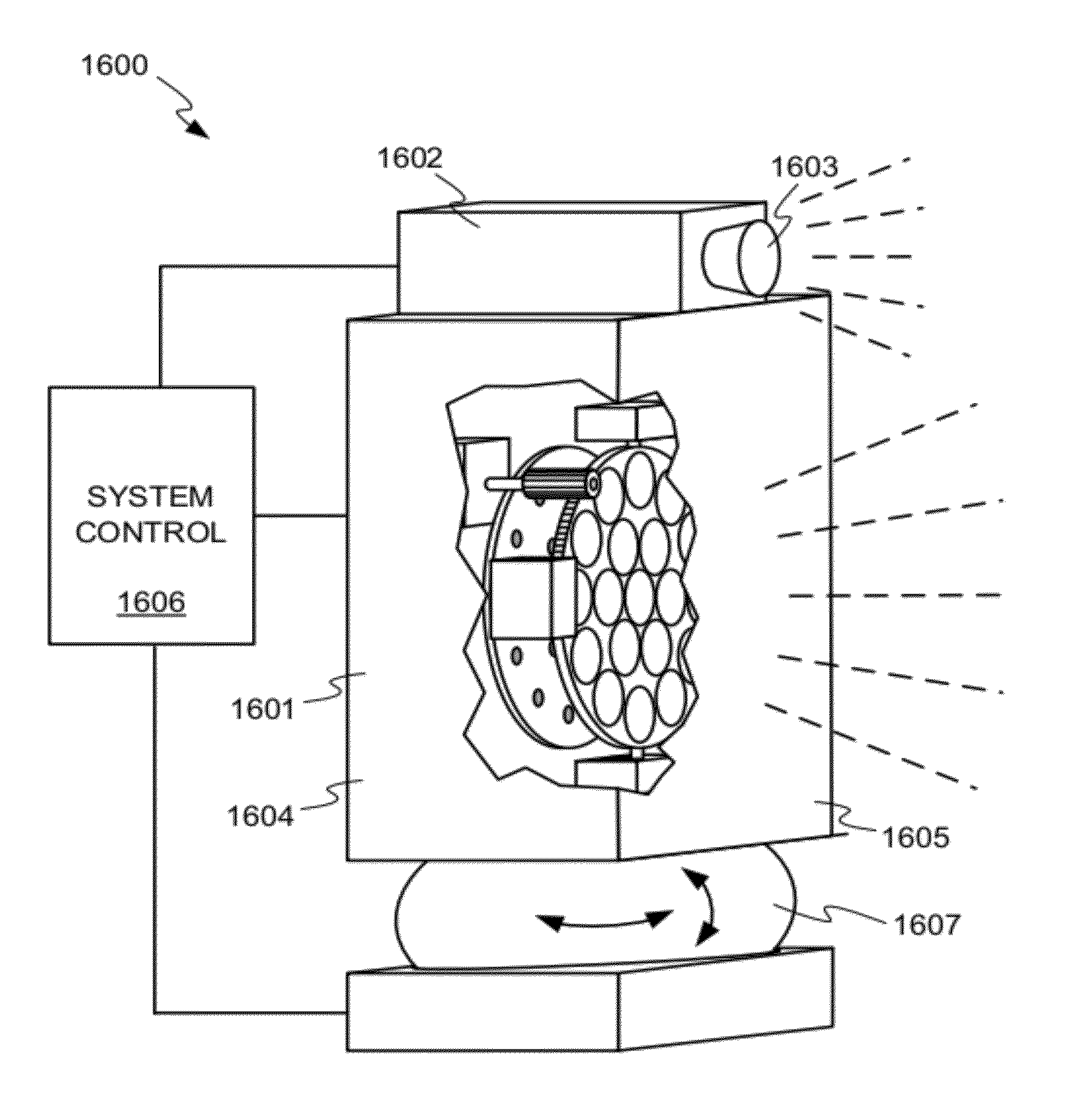
A variable focus illuminator includes an array of light sources and a movable lens plate positioned immediately in front of the array of light sources. The lens plate includes a plurality of lenses that redirect the light produced by the light sources, such that different positions of the lens plate result in different sizes of the field illuminated by the variable focus illuminator. The lens plate may be movable in translation, rotation, or both. The variable focus illuminator may also include a cover plate in front of the movable lens plate, which may also include a plurality of cover plate lenses. The variable focus illuminator may be varifocal, or may include a zoom capability. The variable focus illuminator may be part of a system that includes a camera, and the system may also include a pan / tilt mechanism.

Description

[0001]This application claims priority from U.S. Provisional Patent Application No. 61 / 456,891 filed Nov. 15, 2010 and titled “Variable Focus Illuminator”, the entire disclosure of which is hereby incorporated by reference herein.BACKGROUND OF THE INVENTION[0002]Illuminators are used in conjunction with video security cameras where and when the available light is insufficient for quality observation or recording of the subject scene. Examples of situations that would benefit from the use of an illuminator are unlit or partially lit parking lots, storage facilities, warehouses, office spaces, manufacturing facilities, and the like. These areas of interest for video observation include both indoor and outdoor spaces. For outdoor use, the security camera and the illuminator may be designed to be rugged and weatherproof.[0003]Illuminators used in video security applications may provide visible light, infrared (IR) light, or both. The electronic sensors used in modern video cameras are i...

Claims


Application Information

Patent Timeline
IPC IPC(8): G03B15/03G02B7/02H05B37/02F21V5/00
CPCF21V5/007F21V17/02F21V33/0052F21V33/0076F21Y2101/02F21Y2105/001G02B3/0056G02B3/08G02B7/021G02B7/102G03B15/03G08B13/19626G08B13/19636H05B33/0842F21V5/008F21V14/06F21Y2105/10F21Y2115/10H05B45/30
Inventor STAVELY, DONALD J.
Owner NUOPTIC
Learn More