Dispensing channel pump
a technology of pump and channel pump, which is applied in the direction of pliable tubular containers, single-unit devices, containers, etc., to achieve the effect of promoting convenient access and timely us
- Summary
- Abstract
- Description
- Claims
- Application Information
AI Technical Summary
Benefits of technology
Problems solved by technology
Method used
Image
Examples
example 1
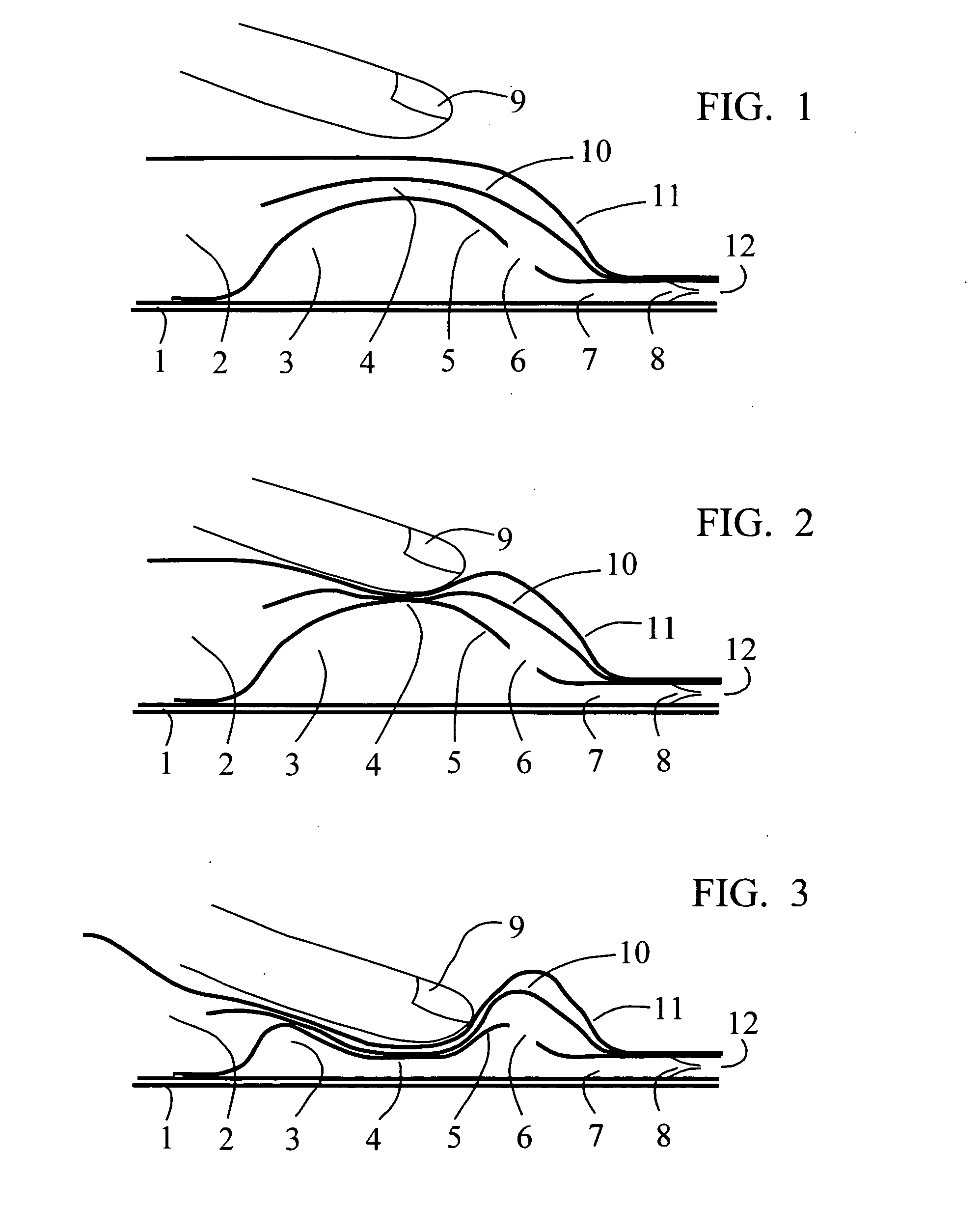
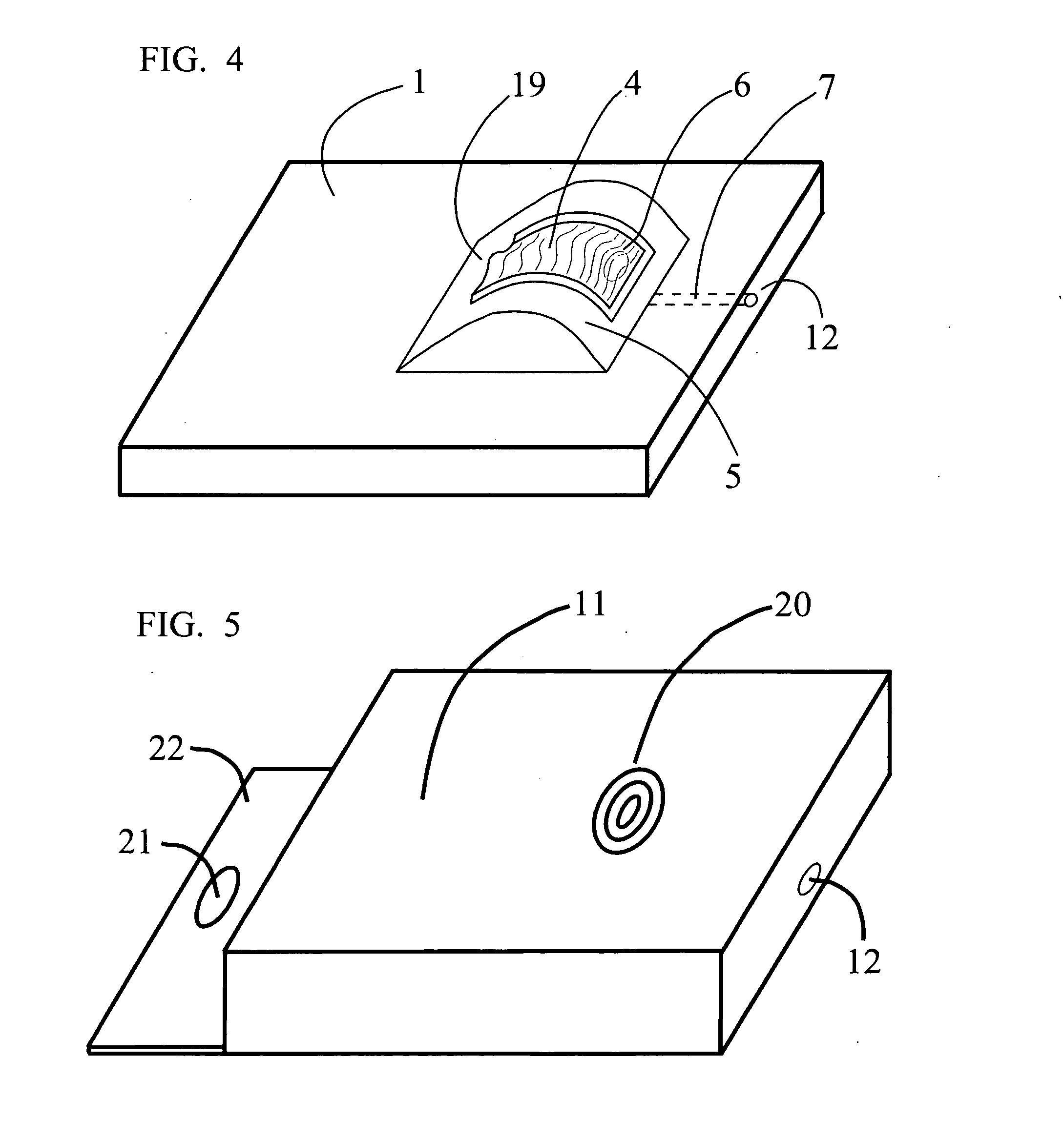
[0024]In FIG. 1 a cut through side view of the pump assembly of a fluid dispenser is illustrated. Comprising elements include a base 1 which is attached by peripheral seal to a fluid reservoir of which a flexible portion of the upper reservoir wall 11 is shown. The reservoir wall 11 fully encloses a fluid material as product contained within the reservoir chamber 2, this fluid is also found in and in fluidic communication with fluid in the channel 4, pump chamber 3, and dispensing channel 7. All fluid is sealed away from the atmosphere so as to exclude fluid product contamination, prevent deterioration, and eliminate quantitative loss. The fluid held within the reservoir 2, channels, and pump chamber 3 has only one outlet to the atmosphere, through a one-way exit valve 8 and out an orifice 12 for dispersal. The valve 8 may consist of any one or more known types including duckbill, check, compression, elastic, flap, reed, spring, and similar one-way mechanisms. All, by their operatio...
example 2
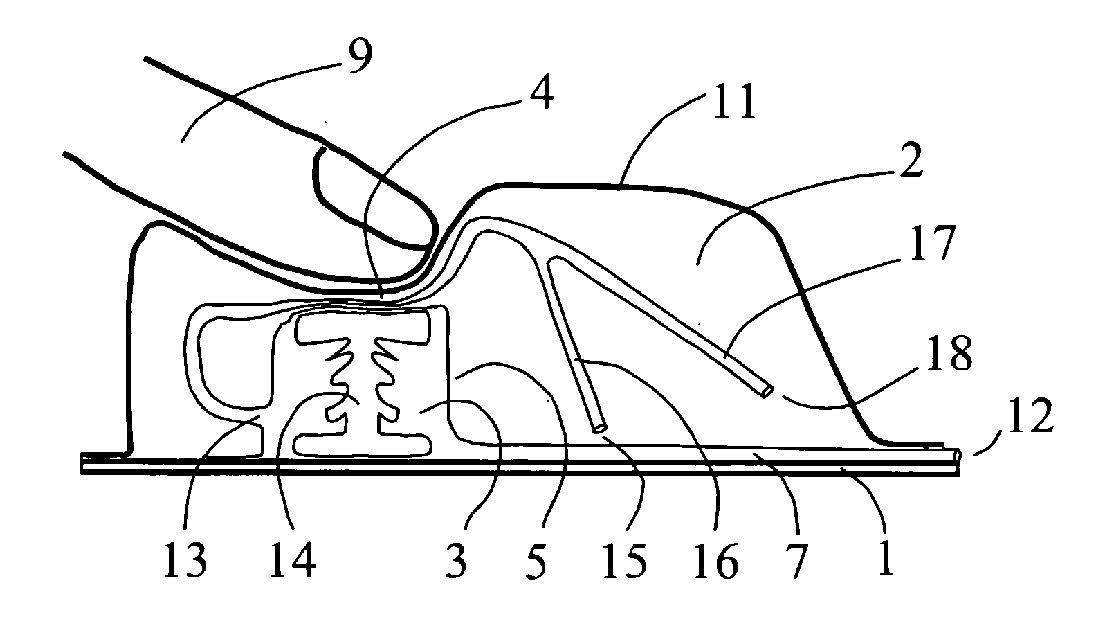
[0030]In FIG. 6 a cut through side view of the pump assembly of a fluid dispenser is illustrated in a fashion similar to FIG. 1. The familiar elements of base 1, reservoir wall 11, pump chamber 3, reservoir chamber 2, dispensing channel 7, orifice 12, channel 4, and pump wall 5 are again shown. Additionally, new features are illustrated which include a channel 4 which is depicted as a pipe whose wall is formed independent of any other pump component and has plural channel inlets formed, in this example, by bifurcated pip extensions defined as a mid pipe 16 and far pipe 17. Each of these pipes terminates in an inlet respectively described as mid inlet 15 and far inlet 18. Various placements of such inlets at diverse locations within the reservoir chamber 2 allows the gathering of fluid product so as to eliminate or greatly reduce irretrievable wastage. Also newly illustrated is a pump element described as a spring 14 which, by its resistive resilient nature, aids in both defining the...
PUM
 Abstract
Description
Claims
Application Information
 - R&D
- Intellectual Property
- Life Sciences
- Materials
- Tech Scout
- Unparalleled Data Quality
- Higher Quality Content
- 60% Fewer Hallucinations
Browse by: Latest US Patents, China's latest patents, Technical Efficacy Thesaurus, Application Domain, Technology Topic, Popular Technical Reports.
© 2025 PatSnap. All rights reserved.Legal|Privacy policy|Modern Slavery Act Transparency Statement|Sitemap|About US| Contact US: help@patsnap.com


