
Continuously variable transmission

a technology of continuous variable transmission and transmission line, which is applied in the direction of gearing details, gearing, transportation and packaging, etc., can solve the problems of lower efficiency performance of cvt and lower fatigue li

Active Publication Date: 2012-05-10
FALLBROOK INTPROP COMPANY
View PDF5 Cites 28 Cited by
  • Summary
  • Abstract
  • Description
  • Claims
  • Application Information

AI Technical Summary

Benefits of technology

"The systems and methods described in this patent have several features that make them useful. These features are not solely responsible for the system's desirable attributes, but rather work together to make it more effective. The technical effects of this patent include improved efficiency, reliability, and overall performance of the system."

Problems solved by technology

High stress exerted on the idler component leads to lower fatigue life and lower efficiency performance of the CVT.

Method used


Image

  • Continuously variable transmission
  • Continuously variable transmission
  • Continuously variable transmission

Examples


Embodiment Construction

” one will understand how the features of the system and methods provide several advantages over traditional systems and methods.

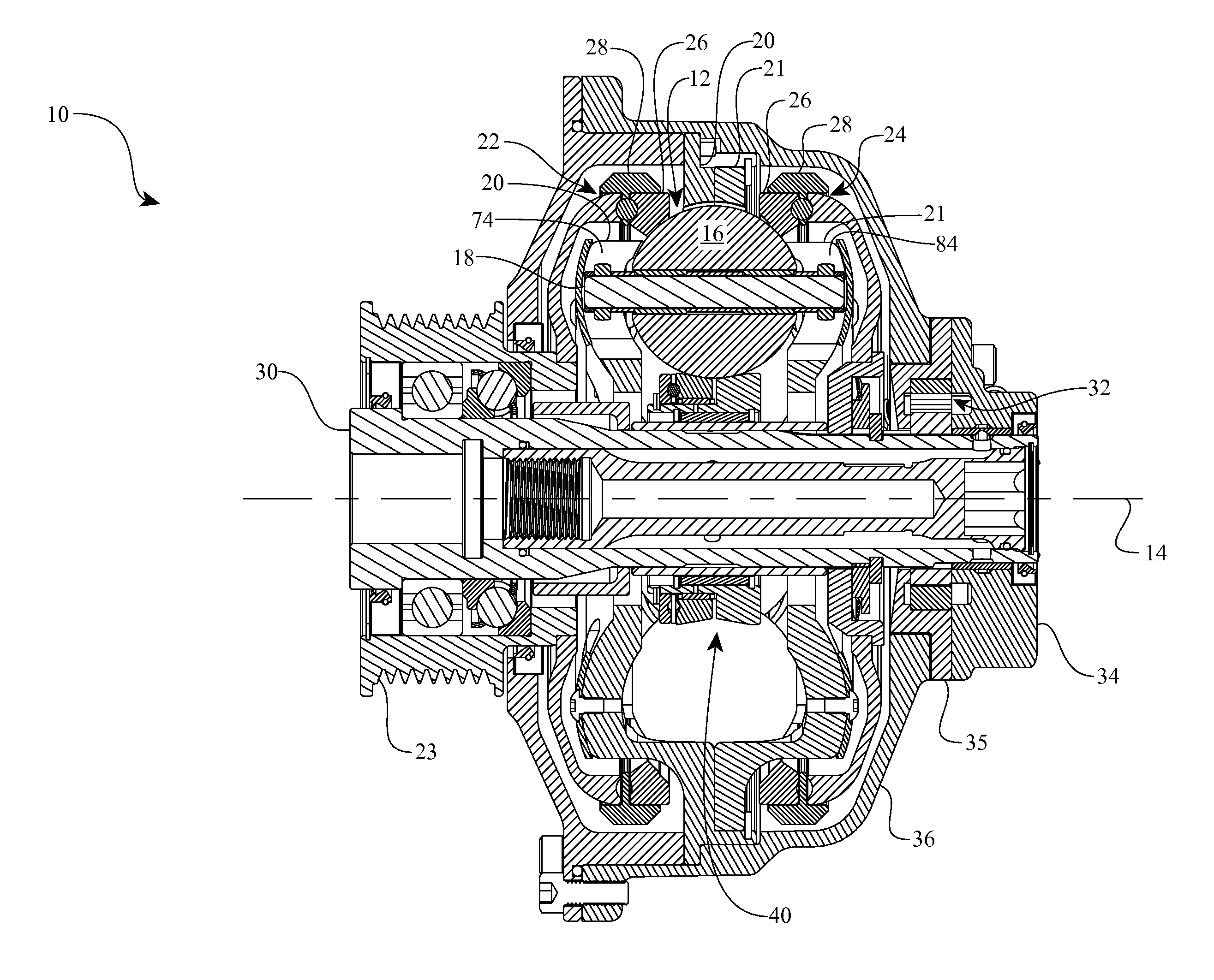
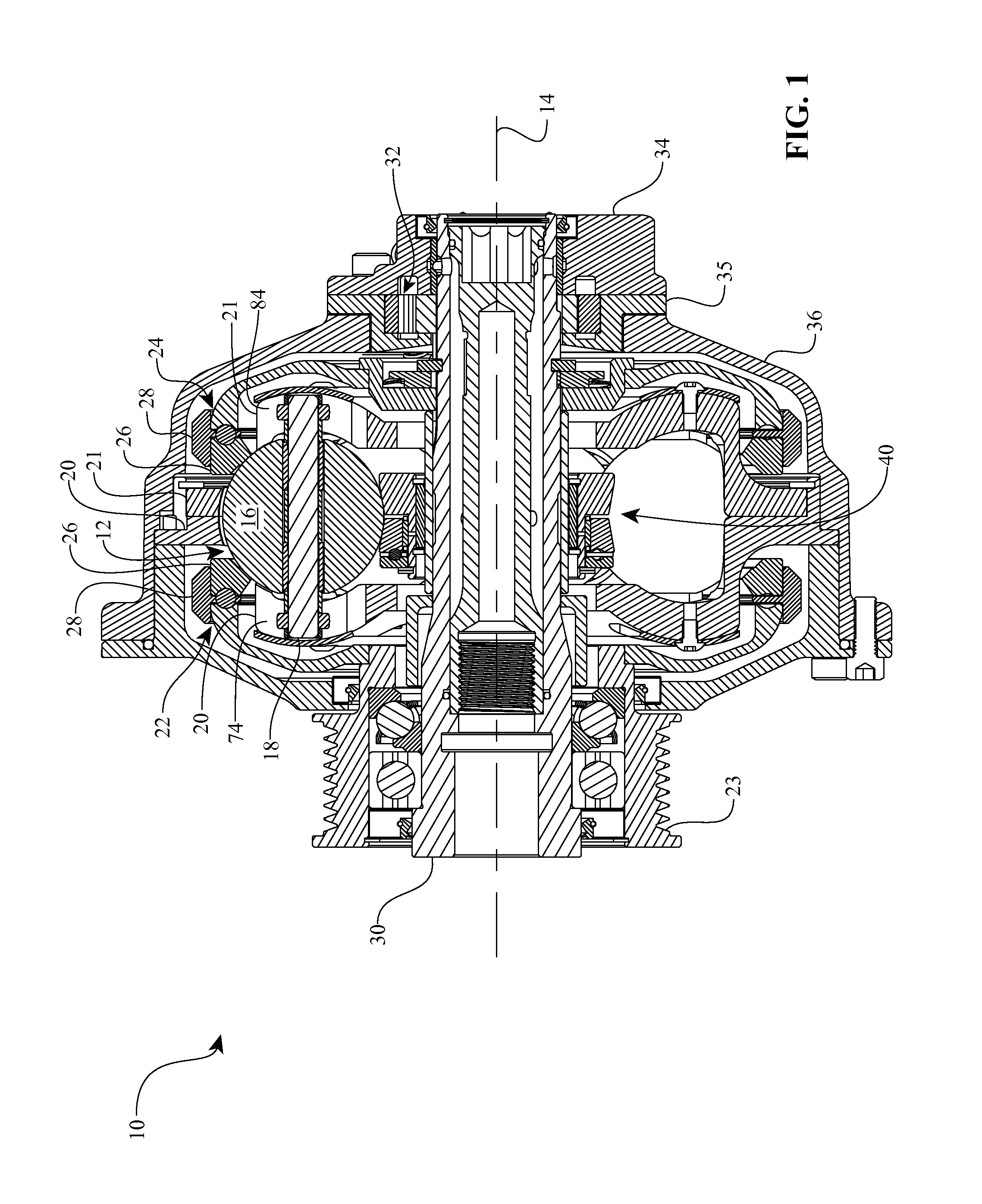
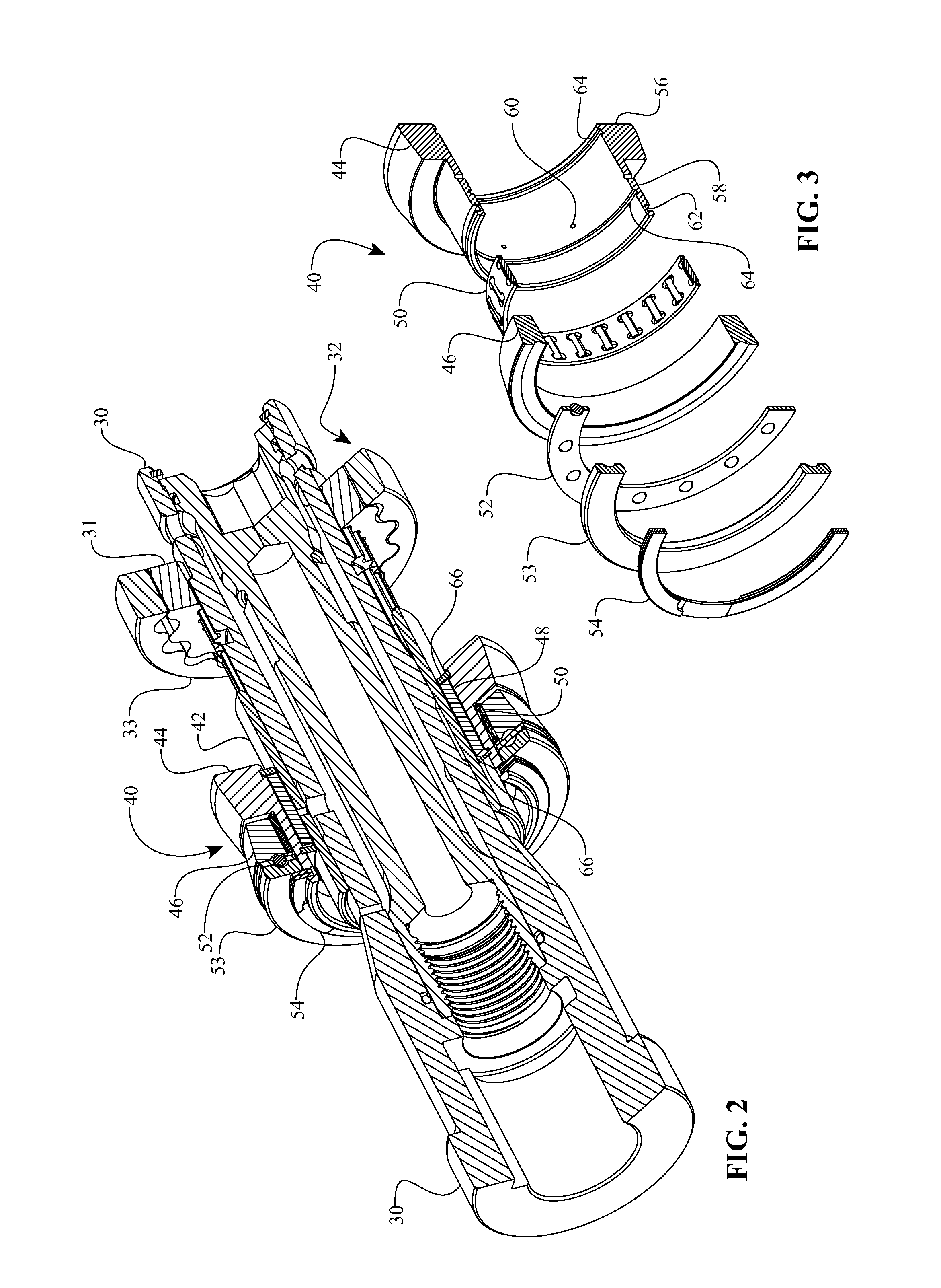
[0008]One aspect of the disclosure relates to a continuously variable transmission (CVT) having a longitudinal axis. In one embodiment, the CVT includes a group of spherical traction planets. Each traction planet has an axle about which it rotates. The axle is configured to tilt with respect to the longitudinal axis. The CVT includes an idler assembly in contact with each of the traction planets. In one embodiment, the idler assembly is located radially inward of each of the traction planets. The idler assembly has first and second rolling elements. The first and second rolling elements are configured to rotate at different speeds corresponding to the tilt of the traction planets.

[0009]Another aspect of the disclosure relates to a continuously variable transmission (CVT) having a group of traction planet assemblies arranged angularly about a longitudinal a...


PUM


Abstract

Disclosed embodiments are directed to components, subassemblies, systems, and / or methods for continuously variable transmissions (CVT). In one embodiment, a CVT has a number of spherical planets in contact with an idler. Various idler assemblies can be used to facilitate to improve durability, fatigue life, and efficiency of a CVT. In one embodiment, the idler assembly has two rolling elements having contact surfaces that are angled with respect to a longitudinal axis of the CVT. In some embodiments, a bearing is operably coupled between the first and second rolling elements. The bearing is configured to balance axial force between the first and second rolling elements. In one embodiment, the bearing is a ball bearing. In another embodiment, the bearing is an angular contact bearing. In yet other embodiments, needle roller bearings are employed.

Description

RELATED APPLICATION[0001]This application claims the benefit of U.S. Provisional Application No. 61 / 412,290, filed on Nov. 10, 2010, which is hereby incorporated by reference in its entirety.BACKGROUND[0002]1. Field of the Invention[0003]This disclosure relates generally to mechanical and / or electro-mechanical power modulation devices and methods. More particularly, this disclosure relates to continuously and / or infinitely variable, planetary power modulating devices, and methods for modulating power flow in a power train or drive, such as power flow from a prime mover to one or more auxiliary or driven devices.[0004]2. Description of the Related Art[0005]Continuously variable transmissions (CVT) having spherical planets such as those generally described in U.S. Pat. No. 7,011,600 to Miller et al, U.S. Pat. No. 5,236,403 to Schievelbusch, or U.S. Pat. No. 2,469,653 to Kopp, typically have a rotatable support member or an idler component in contact with each spherical planet. In some...

Claims


Application Information

Patent Timeline
Patent Type & Authority Applications(United States)
IPC IPC(8): F16H37/02
CPCF16H15/50F16H55/32F16C19/545F16H15/503F16H15/52B62M11/16F16H57/0484F16H57/0487F16H2057/085
Inventor LOHR, CHARLESPOHL, BRAD
Owner FALLBROOK INTPROP COMPANY
Learn More