
Uplink receiving method for a base station and uplink transmitting method for a terminal using a shared wireless resource

a technology of shared wireless resources and receiving methods, which is applied in the direction of digital transmission, wireless commuication services, error prevention, etc., can solve the problem of difficult for the base station to know the accurate buffer status of the terminals, and achieve the effect of reducing the delay of the transmission of the link

Inactive Publication Date: 2012-05-10
ELECTRONICS & TELECOMM RES INST
View PDF4 Cites 54 Cited by
  • Summary
  • Abstract
  • Description
  • Claims
  • Application Information

AI Technical Summary

Benefits of technology

[0023]Accordingly, processes such as an uplink radio resource request between a terminal and a base station, a buffer status report, and uplink radio resource allocation are integrated and reduced so that an uplink transmission delay can be reduced.

Problems solved by technology

However, multiple terminals are within the service area of the base station and provided with various packet services, and thus it is difficult for the base station to know the accurate buffer status of the terminals.

Method used


Image

  • Uplink receiving method for a base station and uplink transmitting method for a terminal using a shared wireless resource
  • Uplink receiving method for a base station and uplink transmitting method for a terminal using a shared wireless resource
  • Uplink receiving method for a base station and uplink transmitting method for a terminal using a shared wireless resource

Examples


Embodiment Construction

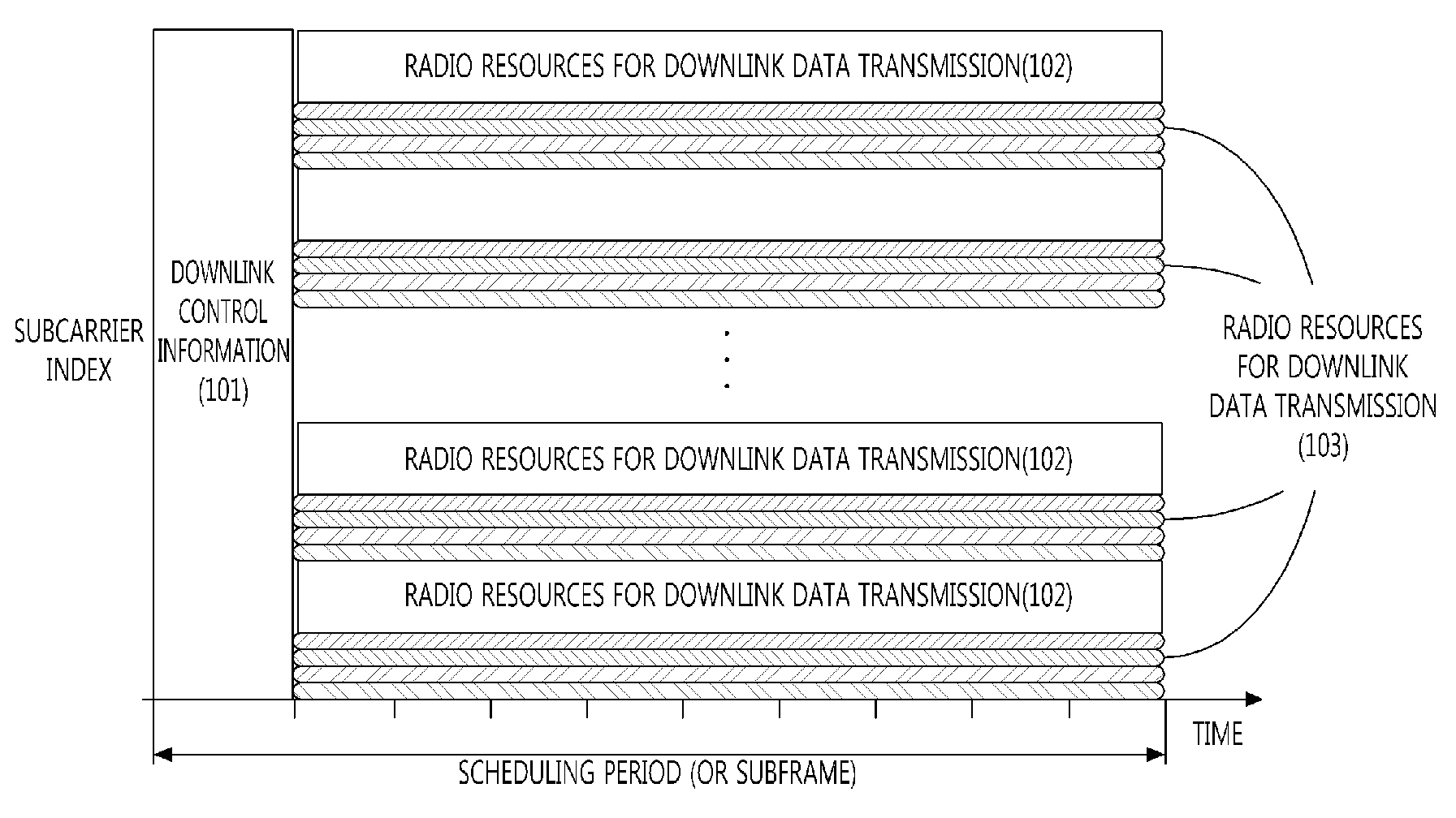
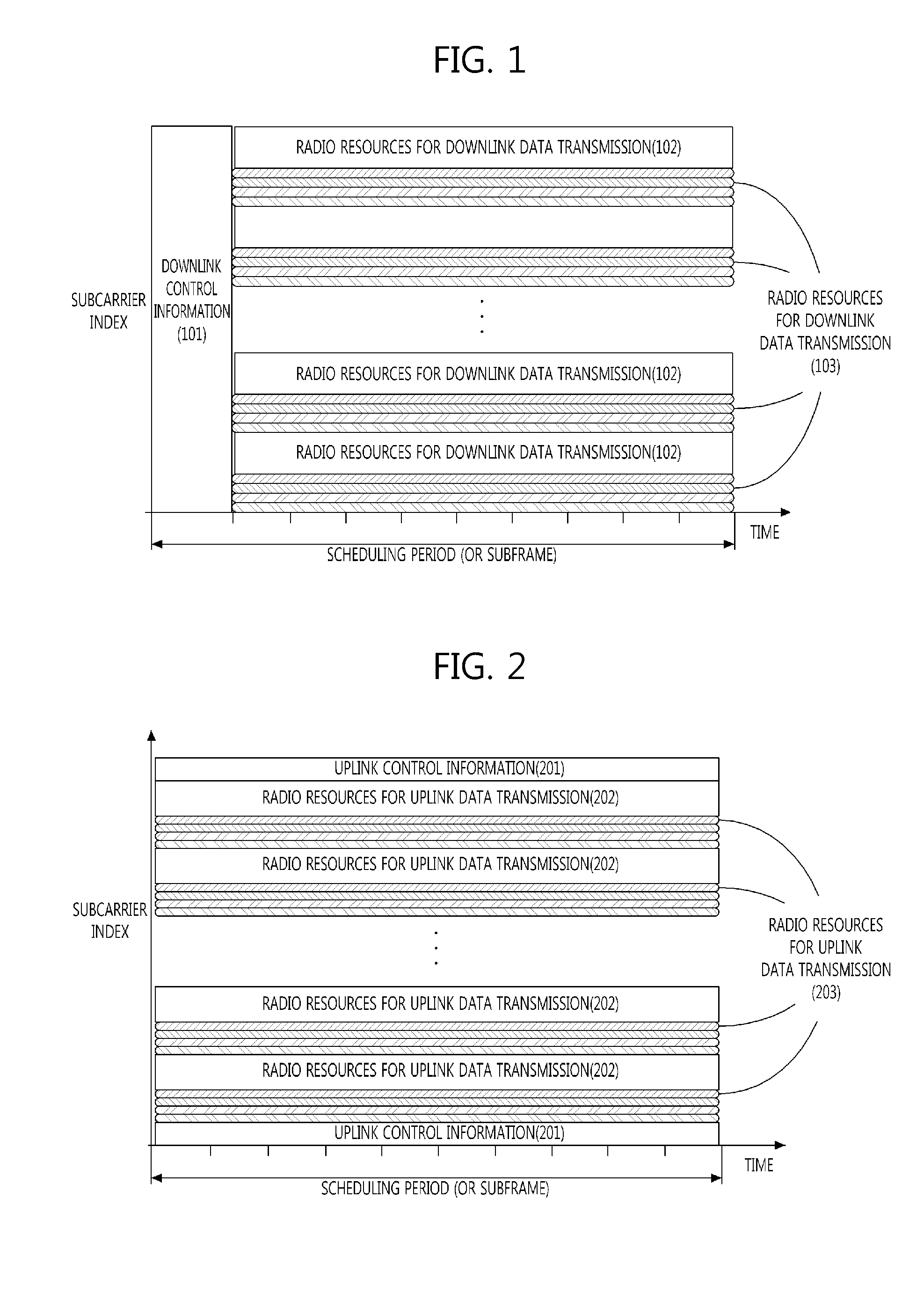
[0031]Example embodiments of the present invention are disclosed herein. However, specific structural and functional details disclosed herein are merely representative for purposes of describing example embodiments of the present invention, however, example embodiments of the present invention may be embodied in many alternate forms and should not be construed as limited to example embodiments of the present invention set forth herein.

[0032]Accordingly, while the invention is susceptible to various modifications and alternative forms, specific embodiments thereof are shown by way of example in the drawings and will herein be described in detail. It should be understood, however, that there is no intent to limit the invention to the particular forms disclosed, but on the contrary, the invention is to cover all modifications, equivalents, and alternatives falling within the spirit and scope of the invention. Like numbers refer to like elements throughout the description of the figures...


PUM


Abstract

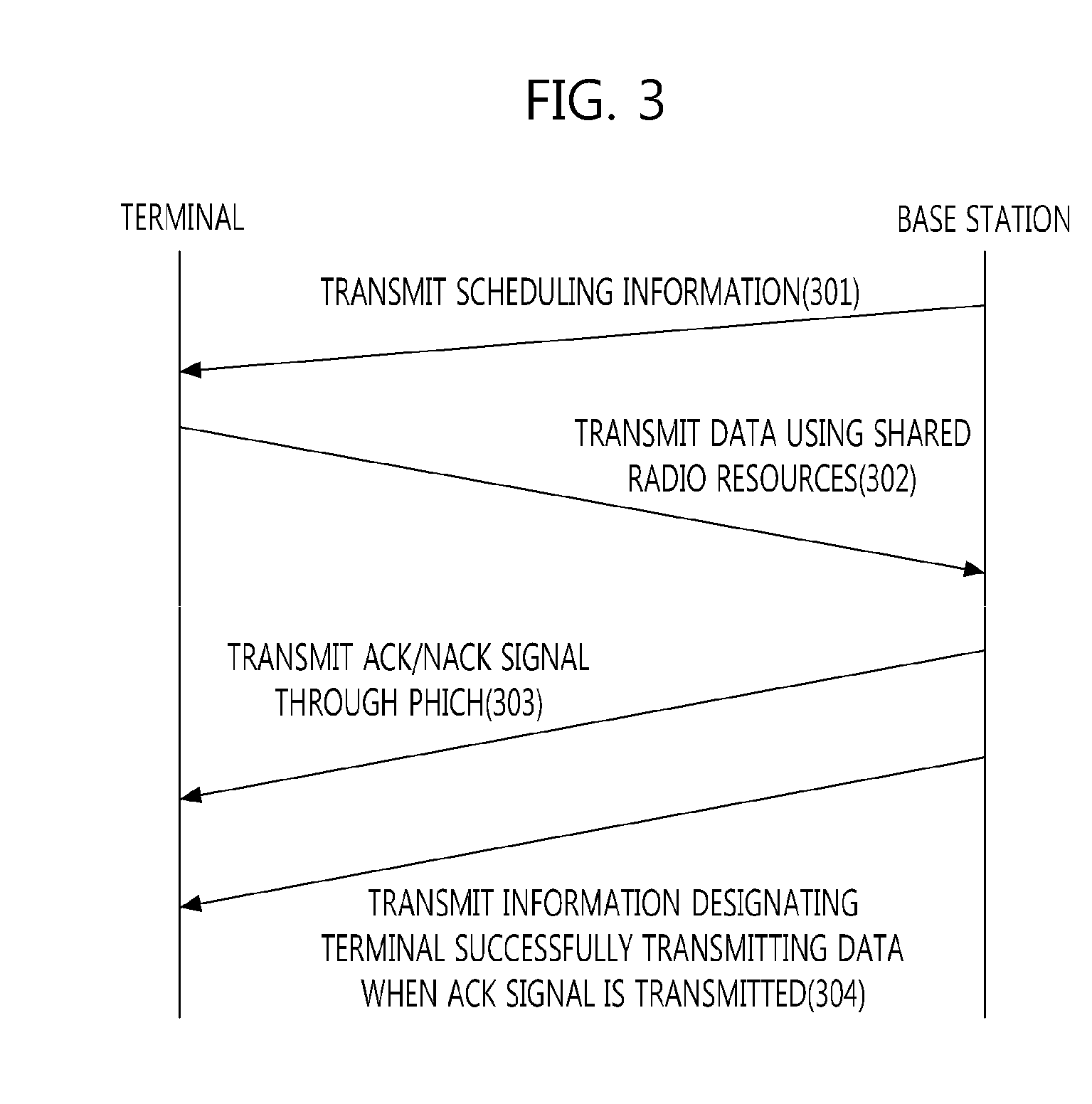
The invention relates to an uplink receiving method for a base station, comprising: a step of transmitting scheduling information for a shared wireless resource to object terminals to which the shared wireless resource is to be allocated, via a downlink control channel using a scheduling identifier; a step of receiving data from at least one terminal from among the object terminals, via the shared wireless resource allocated by the scheduling information; and a step of transmitting data receipt feedback information for at least one terminal which has received data via the shared wireless resource. An uplink transmitting method for a terminal comprises: a step of receiving scheduling information for a shared wireless resource from a base station via a downlink control channel; a step of transmitting data via the shared wireless resource allocated by the scheduling information; and a step of receiving, from the base station, feedback information which indicates whether or not the data transmitted via the shared wireless resource has been successfully received. Consequently, uplink transmission procedures between the terminal and the base station are integrated and simplified to reduce uplink transmission latency.

Description

TECHNICAL FIELD[0001]The present invention relates in general to an uplink transmission method of a terminal and an uplink reception method of a base station in a cellular system, and more specifically to an uplink transmission method of a terminal and an uplink reception method of a base station using shared radio resources which can reduce an uplink transmission delay.BACKGROUND ART[0002]In a conventional cellular system, dedicated radio resources are allocated to a random terminal.[0003]In other words, in a circuit-based cellular system, when a communication connection for data exchange between a terminal and a base station is set, a dedicated channel is allocated to enable data transmission regardless of whether or not there is data to be transmitted by the terminal.[0004]Also in a packet-based orthogonal frequency division multiplexing (OFDM) (or orthogonal frequency division multiple access (OFDMA)) cellular system, such as a third generation partnership project (3GPP) long te...

Claims


Application Information

Patent Timeline
Patent Type & Authority Applications(United States)
IPC IPC(8): H04W74/04H04W72/04
CPCH04L1/1861H04W72/121H04L5/0094H04L5/0007
Inventor KIM, JAE HEUNG
Owner ELECTRONICS & TELECOMM RES INST
Learn More