
Packet transfer method and device

a technology of packet transfer and transfer method, applied in the field of packet transfer method and device, can solve the problems of increasing hardware scale to a large scale, causing delay time, and causing delay, and achieve the effect of reducing the transfer delay

Inactive Publication Date: 2005-11-03
FUJITSU LTD
View PDF11 Cites 53 Cited by
  • Summary
  • Abstract
  • Description
  • Claims
  • Application Information

AI Technical Summary

Benefits of technology

[0042] It is accordingly an object of the present invention to provide a method and device which can reduce a transfer delay and can transfer a packet with small-scale hardware when the packet to which fragmentation is performed after encapsulation is received.
[0048] As mentioned above, in the present invention, the decapsulation is performed with defragmentation processing being skipped, thereby enabling the defragmentation to be performed at a node which will finally receive the packet. Namely, since the decapsulation is enabled by operating the header with a datagram portion of the fragmented packet being unchanged, it becomes possible to eliminate a transfer delay at the time of assembling packets associated with the defragmentation and an increase of a hardware scale.

Problems solved by technology

The biggest problem at the time of performing such defragmentation processing with hardware is a transfer delay time which occurs at the time of assembling the packet.
Therefore, when the packet is transmitted while receiving traffic is high, congestion occurs and a queuing time is required, which leads to a further addition of the delay time.
As for another problem, a hardware scale is increased to a large scale due to such buffering.
If the buffering is performed to the packet by an individual buffer method, an enormous buffer (memory) is required.
If a common buffer method is applied, its hardware arrangement becomes complicated.

Method used


Image

  • Packet transfer method and device
  • Packet transfer method and device
  • Packet transfer method and device

Examples


Embodiment Construction

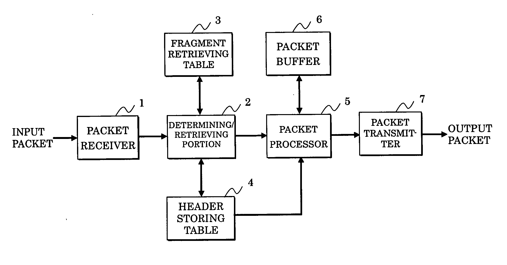
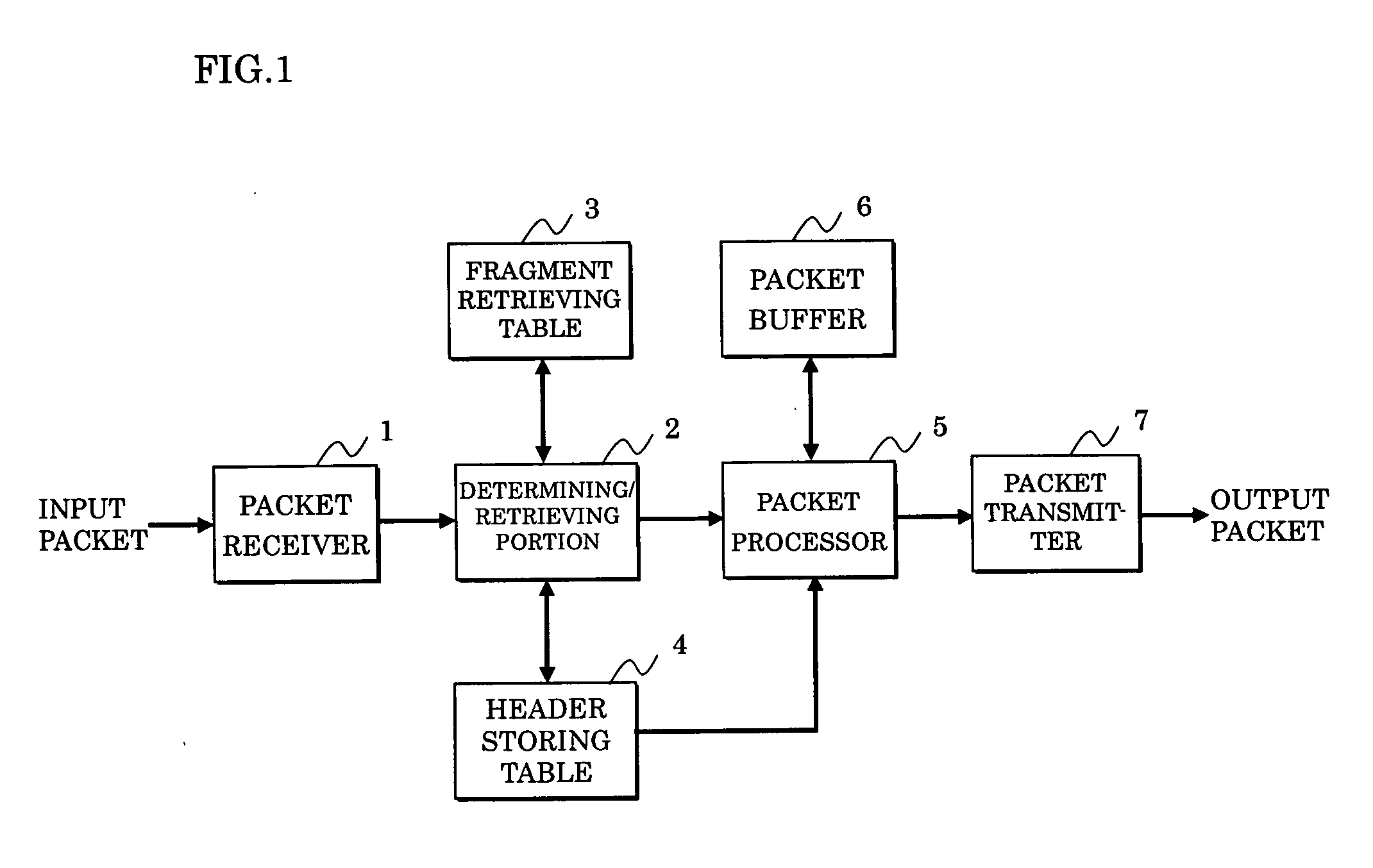
[0090]FIG. 1 shows a packet transfer device used for executing a packet transfer method according to the present invention, which specifically corresponds to the node (or router) 20 in the IPv6 network shown in FIG. 10.

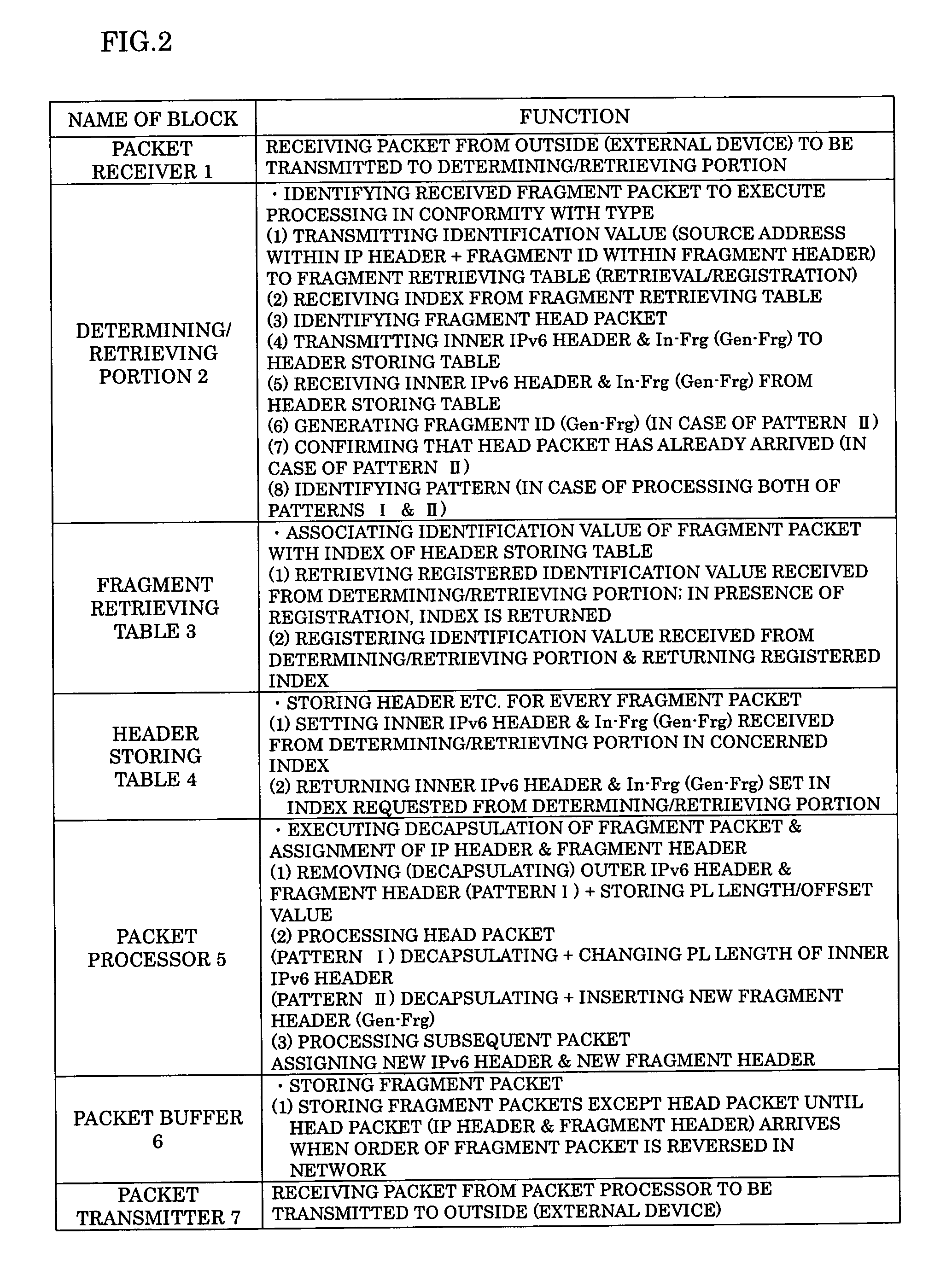
[0091]FIG. 2 shows a function of each block of the packet transfer device shown in FIG. 1. A packet receiver 1 receives a packet from outside (external device) such as a node (router) 10 shown in FIG. 10 to be transmitted to a determining / retrieving portion 2.

[0092] The determining / retrieving portion 2 identifies a received fragment packet, and is connected to a fragment table 3 and a header storing table 4 for executing processing in conformity with a type of the packet.

[0093] The fragment retrieving table 3 is a table associating the identification of the fragment packet with an index of the header storing table 4. The header storing table 4 stores the header or the like for every fragment packet per index.

[0094] The determining / retrieving portion 2 is further c...


PUM


Abstract

In a packet transfer method and device which can reduce a transfer delay and transfer a packet with a small-scale hardware when the packet to which fragmentation is performed after encapsulation is received, a head packet and a subsequent packet are detected from received packets to which the fragmentation is performed after the encapsulation, an inner header of the head packet detected is stored and then decapsulated, the inner header is changed in conformity with the decapsulation, the subsequent packet is further decapsulated, and the inner header of the head packet changed as mentioned above and a fragment offset value in conformity with the fragmentation are assigned to each packet to be outputted.

Description

BACKGROUND OF THE INVENTION [0001] 1. Field of the Invention [0002] The present invention relates to a packet transfer method and device, and in particular to a packet transfer method of receiving and transferring a packet to which fragmentation is performed after encapsulation in an IPv6 or IPv4 network, and a packet transfer device such as a node and a router realizing the method. [0003] 2. Description of the Related Art [0004]FIG. 10 shows a generally known IPv6 network, and this example shows an arrangement in which a packet transmitted from a node 10 is transferred to a node 30 through a node 20. [0005] In this case, an IP tunnel TN using an encapsulated IP packet (IP-in-IP packet) is provided between the nodes 10 and 20. The node 10 generates a packet PKT2 that is a packet (composed of an inner header and data) PKT1 encapsulated by an outer header in order to pass through the IP tunnel TN, and transmits the packet to the node 20. [0006] It is to be noted that the “inner header...

Claims


Application Information

Patent Timeline
Patent Type & Authority Applications(United States)
IPC IPC(8): H04L47/43
CPCH04L29/06H04L69/22H04L45/40H04L45/00H04L9/40
Inventor FUKUDA, KENJI
Owner FUJITSU LTD
Learn More