Self-cleaning of optical surfaces in low-pressure reactive gas environments in advanced optical systems

Inactive Publication Date: 2012-05-10
UNIV OF COLORADO THE REGENTS OF
View PDF5 Cites 10 Cited by
  • Summary
  • Abstract
  • Description
  • Claims
  • Application Information

AI Technical Summary

Benefits of technology

[0009]It is an object of the present invention to provide apparatus and methods for self-cleaning of optical elements in sealed environments over a wide range of operating optical frequencies. The introduction of a low-pressure oxygen background into a vacuum chamber can be used to preclude deposition on optics in a vacuum system, in particular in the case of laser systems where light in the optical system is intense but is not predominantly EUV, and where no metal coating or other special preparation of the optics in the system is required. This oxygen backfill serves to keep optics clean even when the only light incident on an optical surface is IR / visible, and thus generally will not directly ionize hydrocarbons or the oxygen gas introduced into the chamber. The result is that a low-pressure oxygen backfill greatly extends the duration between physical or active-cleaning of the optics in optical systems. This is an extremely useful realization, especially for ultrafast optical systems that would otherwise simply be impractical for routine laboratory use.

Problems solved by technology

These configurations are very useful, but as average or peak power loads increase, power degradation becomes a problem due to deposition on optics.
These systems are extremely sensitive to contamination resulting in degraded transmission or reflection of the optics, often also leading to damage of optical coating / surfaces.
These hydrocarbons tend to deposit on the optical surfaces where the high-intensity beams are incident, resulting in coating of the optical surfaces.
However, since these systems are completely sealed from the environment, these active cleaning methods require unsealing the optical system, often interrupting operation, or the use of a dedicated and expensive cleaning system for the vacuum system.
(U.S. Pat. No. 6,664,554 B2) This work, however, specifies the use of “a metal disposed on the surface of the optic, wherein said metal protects the optic surface against oxidation.” Furthermore, reduction in practice in this work was limited to the use of EUV optical systems.
Visible / IR light photons are not energetic enough to cause this decomposition.
The power output was observed to degrade over a time of hours.

Method used


Image

  • Self-cleaning of optical surfaces in low-pressure reactive gas environments in advanced optical systems
  • Self-cleaning of optical surfaces in low-pressure reactive gas environments in advanced optical systems
  • Self-cleaning of optical surfaces in low-pressure reactive gas environments in advanced optical systems

Examples


first embodiment

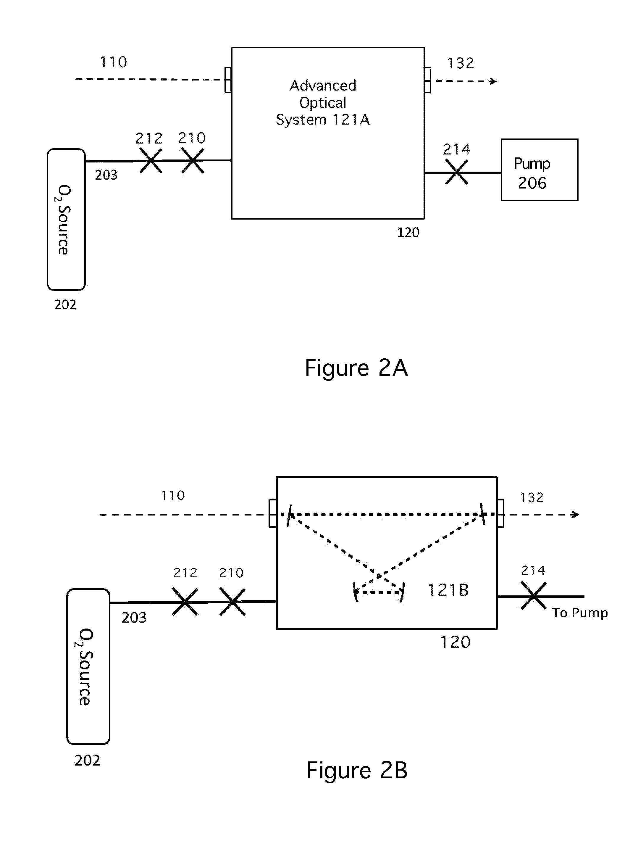
[0020]Pumping causes a vacuum to form in vacuum chamber 120. After the vacuum is created, a small amount of oxygen / or other reactive species 203 is inserted into vacuum chamber 120. In a first embodiment, valves 210 and 214 are closed and chamber 210 is sealed for some period of time while in use. The oxygen source may be disconnected from vacuum chamber 120 via connector 212, if desired. Pump 206 may also be disconnected. Generally, an input pump beam 110 is provided to the vacuum chamber 120. The optics within vacuum chamber 120 amplify pump beam 110 and provide an amplified output beam 132.

second embodiment

[0021]In a second embodiment, chamber 120 is evacuated, the oxygen backfill in inserted, and the optical system is run for a period of time. Then, chamber 120 is re-evacuated and sealed. Tests have shown that in some cases the backfilled O2 gas can be evacuated from the chamber after an extended period of operation, once all contaminants have been consumed by the backfilled gas. A period of several weeks of operation has proved to be sufficient in one test.

third embodiment

[0022]In a third embodiment, pumping is continuous, and oxygen 202 is added continuously as well, at such a rate that the desired pressure is maintained. In this case, valves 210, 214 and are not closed and may not need to be present.

[0023]The oxygen backfill of the present invention is most useful in systems wherein the power level is high enough to cause contamination, for example peak powers exceeding 100 MW for an amplifier, or over 5 mJ pulse energy for a compressor, over a spot size of 5 mm or less. A wide range of oxygen backfill pressures provides a benefit, from >10 torr down to as low as 10−4 torr. Pressures between 0.1 torr and 2 torr have proven to work especially well. In a cryogenic chamber, the initial pressure of (for example) 2 torr is reduced to around 10−2 torr because of gas condensation on the low temperature components. This still works well, because as oxygen is used up in the system, the remaining oxygen becomes available.

[0024]FIG. 2B is a block diagram simi...


PUM


Abstract

Apparatus and methods for self-cleaning of optical elements in sealed environments over a wide range of operating optical frequencies prevent long-term power degradation by introducing low-pressure backfill of a reactive gas such as oxygen into a vacuum chamber containing the optical elements. The backfill pressure is preferably between 10−4 torr and 10 torr, and generally between 0.1 torr and 2 torr at room temperature. The vacuum chamber may be continuously evacuated and backfilled, or may be sealed after evacuation and backfill is performed.

Description

BACKGROUND OF THE INVENTION[0001]1. Field of the Invention[0002]The present invention relates to self-cleaning of optical elements in advanced optical and laser systems. In particular, the present invention relates to self-cleaning of optical elements in vacuum chambers accomplished by adding a reactive gas to the vacuum chamber.[0003]2. Description of Related Art[0004]Advanced optical and laser systems operating in the wavelength ranging from far infrared to extreme ultraviolet (EUV) are making increasing use of vacuum or sealed environments for part or even all of their optical components. For example, high average power laser systems make use of aggressively cooled laser media, where a laser crystal is placed in a vacuum cell and kept at low temperature (often cryogenic <150K) to increase the thermal conductivity, and thus decrease the laser-induced thermal lensing of the laser medium. Previous work with common inventors to the present application shows several embodiments of ...

Claims


Application Information

Patent Timeline
IPC IPC(8): G02B23/16
CPCH01S3/0007H01S3/042H01S3/027
Inventor ZHANG, XIAOSHIKAPTEYN, HENRY C.
Owner UNIV OF COLORADO THE REGENTS OF
Why Eureka
Try Eureka