Method and apparatus for automatic network stabilization in electric power supply systems using at least one converter

a technology of automatic network stabilization and electric power supply system, which is applied in the direction of power oscillation reduction/prevention, electric power transfer ac network, instruments, etc., can solve the problems of weak ac grid, impending voltage collapse, and prone to voltage instability, so as to avoid voltage and angle instability, reliable and efficient power supply system

Inactive Publication Date: 2012-05-10
KUEHN WALTER
View PDF2 Cites 47 Cited by
  • Summary
  • Abstract
  • Description
  • Claims
  • Application Information

AI Technical Summary

Benefits of technology

[0029]Contrary to the above described state-of-the-art methods of voltage dependent current order limiting and event actuated power order reduction the present invention detects reliably voltage and transmission angle instability and it protects against voltage collapse and loss of synchronism irrespective of whatever network changes will take place in the future. Furthermore the converter power adapts itself to maximum transferable network power thus providing maximum efficiency.
[0032]The invention provides for a reliable and efficient power supply system using line-commutated and / or self-commutated converters by avoiding voltage and angle instability with an automatic adaption of the converter power to the maximum transferrable network power.

Problems solved by technology

Weak AC grids are prone to voltage instability and subsequent voltage collapse if there is a reactive power unbalance.
Voltage instability designates a power system state where the profile of node voltages cannot be kept above a certain desired voltage level.
If further decline of AC voltage cannot be stopped voltage collapse is impending.
Voltage collapse can occur, e.g., in connection with reactive power supply by capacitors, stalling asynchronous motors, over-excitation limitation of synchronous generators or if consumer load voltages are controlled via on-load transformer tap changers.
This, however, cannot be guaranteed for the future where grid expansion changes the unstable operating regions.
Then reduction of the short circuit power capacity through an unexpected fault or unplanned switching event may cause unstable conditions and voltage collapse if no countermeasures are taken.
VDCOL is not always reliable since for very weak converter connection points the depression of AC voltage at the stability limit is not high enough to actuate VDCOL.
With ongoing installations of renewable generation facilities and corresponding changes of the load flow it will be difficult if not impossible to keep track of necessary modifications of the power reduction schedule.
After all it can be stated: presently implemented real-time controls do not reliably prevent voltage collapse when operating on a weak AC grid.
Another type of instability relates to the transmission angle of the network the converter is connected to.
This can be considered as a major problem in future power grids if not adequately addressed and cured.
Transmission angle instability can lead to loss of synchronism.
The currently envisaged use of Voltage Phasor Measurements via the Global Positioning System (GPS) cannot be considered as remedial measure in connection with converters since a state estimator including converters, converter based transmission systems and controls, particularly control limits, is not available at the time being.
However, a digital computer study conducted for the present invention showed that also self-commutated converters can cause instability in connection with weak AC grids.
However, the real power supplied by the inverter can not become larger than the MTP-level.
Because the controller does not know the value of the MTP-level it will increase the DC current beyond the MTP-point and actually decrease the real power.
The AC voltage magnitude is, therefore, no proper criterion to predict an impending instability.
1-b) transmission angle instability occurs in both the cases, for fully controllable AC terminal voltage as well as for limited control.
Considering the immense consequences of outages for economy and daily life these investigations are necessary and urgent, particularly in light of the planned power generation additions using large amounts of wind power and in contrast to this, the inadequacy of the actual power grids.
Loss of revenues can sum up to millions of dollars for such systems as the WSCC grid if outages last several hours.
The coupling of the transmission angle of a parallel AC / DC transmission with the AC terminal voltage of the converters introduces even more complexity into the problem then a pure DC transmission does.
The subsequent assessment of their meaning for converter equipped power systems shows that these patents as to the judgment of the author are not usable for an avoidance of voltage collapse in AC / DC systems.
This does not cover static unbalance of power demand and transferable power which is the reason for steady state voltage instability and following dynamic voltage collapse.
However, selection of the margin involves heuristics, i.e., the estimation of closeness to instability is not secure.
Also it is doubtful whether the method can be applied for converters at all because of control limits becoming effective at certain operational conditions leaving no time for the necessary estimation process.
However, specific converter related methods and apparatus for automatic voltage and transmission angle stabilization are in no aspect addressed and clarified, particular the problem of voltage collapse, the underlying destabilizing phenomena and related concrete mitigating converter implemented methods and means are no subject in that material.
According to the current state of the art there is no secure method available detecting instability of the line-commutated or self-commutated converter and conducting an operation with maximum transferrable network power.

Method used


Image

  • Method and apparatus for automatic network stabilization in electric power supply systems using at least one converter
  • Method and apparatus for automatic network stabilization in electric power supply systems using at least one converter
  • Method and apparatus for automatic network stabilization in electric power supply systems using at least one converter

Examples


Embodiment Construction

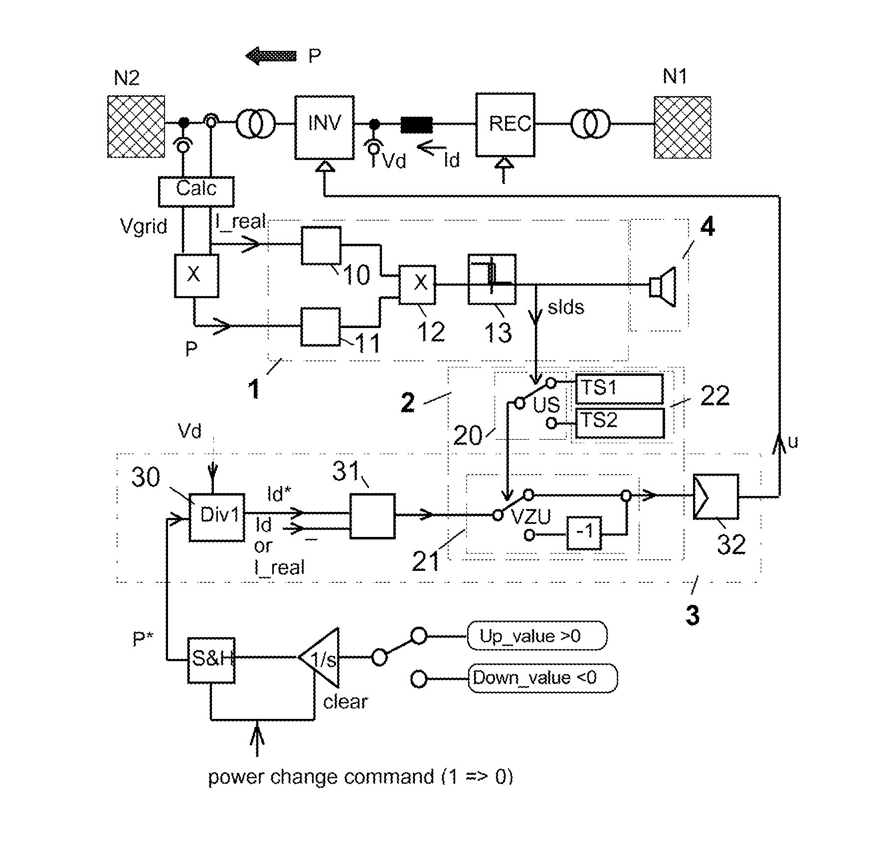
[0101]The present invention comprises two main aspects:[0102]a) Stability analysis which runs in parallel to normal converter controls and which detects the operating status, i.e. whether the current operating point is stable or unstable and[0103]b) an automatic stabilizing control augmenting normal converter power control while using a stability limit detection signal determined through preceding stability analysis

[0104]Since the stability relevant voltage / power interrelationships for current sourced line-commutated and voltage sourced self-commutated converters are different both these devices are dealt with separately despite of common features and properties of the invention.

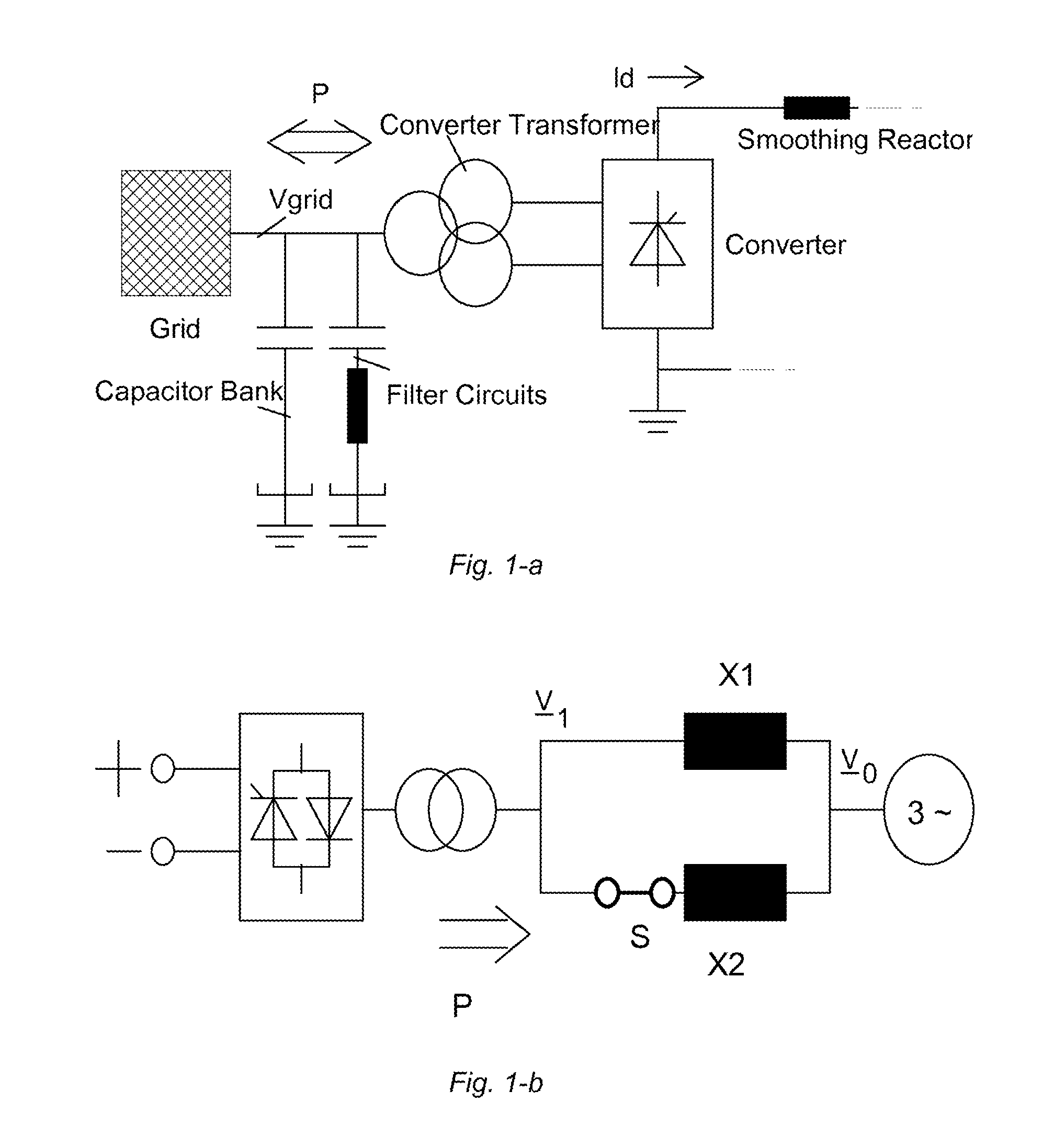
Line-Commutated Converter

[0105]Starting with the line-commutated converter the core idea behind the present invention relates to the fact that at minimum firing angle, resp. extinction angle, a decrease of AC voltage causes a decrease of DC voltage and a corresponding decrease of DC power. The DC current con...


PUM


Abstract

Method and apparatus for automatic stabilization of an electric power supply network system comprising a network and at least one converter adapted to exchange maximum transferrable power with the network by changing the real current through a stabilizing controller, whereby the necessary direction of current change is determined through real-time stability analysis.

Description

CROSS REFERENCE TO RELATED APPLICATIONS[0001]This application is a continuation of International Application No. PCT / EP2010 / 055076, filed on Apr. 16, 2010, which claims priority to German Application No. 10 2009 017 116.9, filed on Apr. 16, 2009 and German Application No. 10 2009 042 865.8, filed on Sep. 24, 2009, the contents of each of which are incorporated herein by reference.TECHNICAL FIELD[0002]The present invention is directed to a method and apparatus for automatic network stabilization in electric power supply systems using at least one converter, and more particularly to prevention of voltage collapse and loss of synchronism.BACKGROUND[0003]Expansion of electric power grids with renewable energies will see an increased utilization of power converters for generation, transmission and energy storage. In order to keep the power system operable and highly reliable steady state voltage and transmission angle stability have to be ensured besides transient stability. These fundam...

Claims


Application Information

Patent Timeline
Patent Type & Authority Applications(United States)
IPC IPC(8): G05F3/00
CPCH02J3/24Y02E60/60H02J3/36
Inventor KUEHN, WALTER
Owner KUEHN WALTER
Why Eureka
Try Eureka