
Method and system for optical network smart timer management via delay measurement between spans

a technology of optical network and delay measurement, applied in the field of communication networks, can solve the problems of slow dynamic connection setup time, loss of control plane packets or loss of control plane connectivity, and inability to meet the needs of the network, etc., and achieve the effect of slowing down the mesh restoration and dynamic connection setup time and ensuring the continuity of the start-of-frame location

Active Publication Date: 2012-05-03
CIENA
View PDF3 Cites 18 Cited by
  • Summary
  • Abstract
  • Description
  • Claims
  • Application Information

AI Technical Summary

Problems solved by technology

If the ODUk circuit is switched or replaced by a maintenance signal, a discontinuity in the start-of-frame location, referred to as frame slip, is inevitable.
Discontinuities or frame slips can result in loss of control plane packets or in loss of control plane connectivity.
Using timer and retry attempts at an application layer results in slower mesh restoration and slower dynamic connection setup time, because they involve using pre-defined timer durations between spans that are longer than necessary.
Identifying an accurate timer value is often difficult, so network operators tend to select timers based on worst case delays.

Method used


Image

  • Method and system for optical network smart timer management via delay measurement between spans
  • Method and system for optical network smart timer management via delay measurement between spans
  • Method and system for optical network smart timer management via delay measurement between spans

Examples


Embodiment Construction

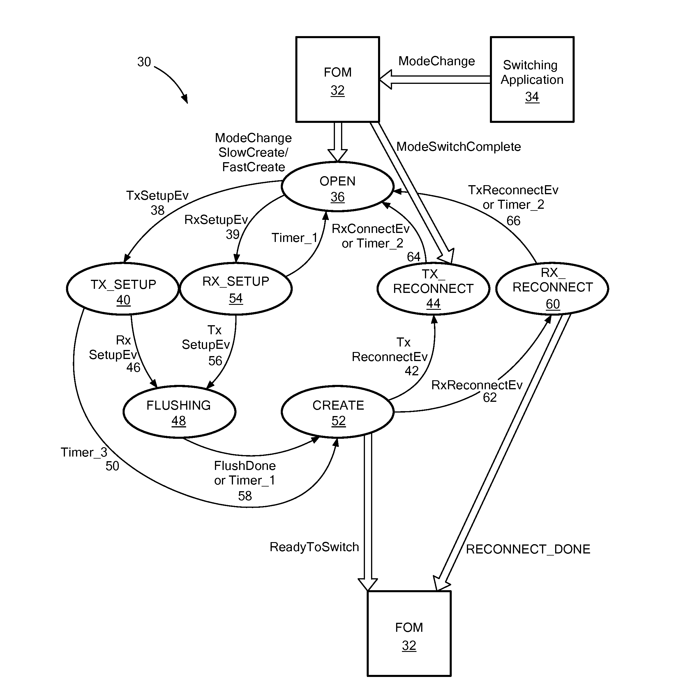
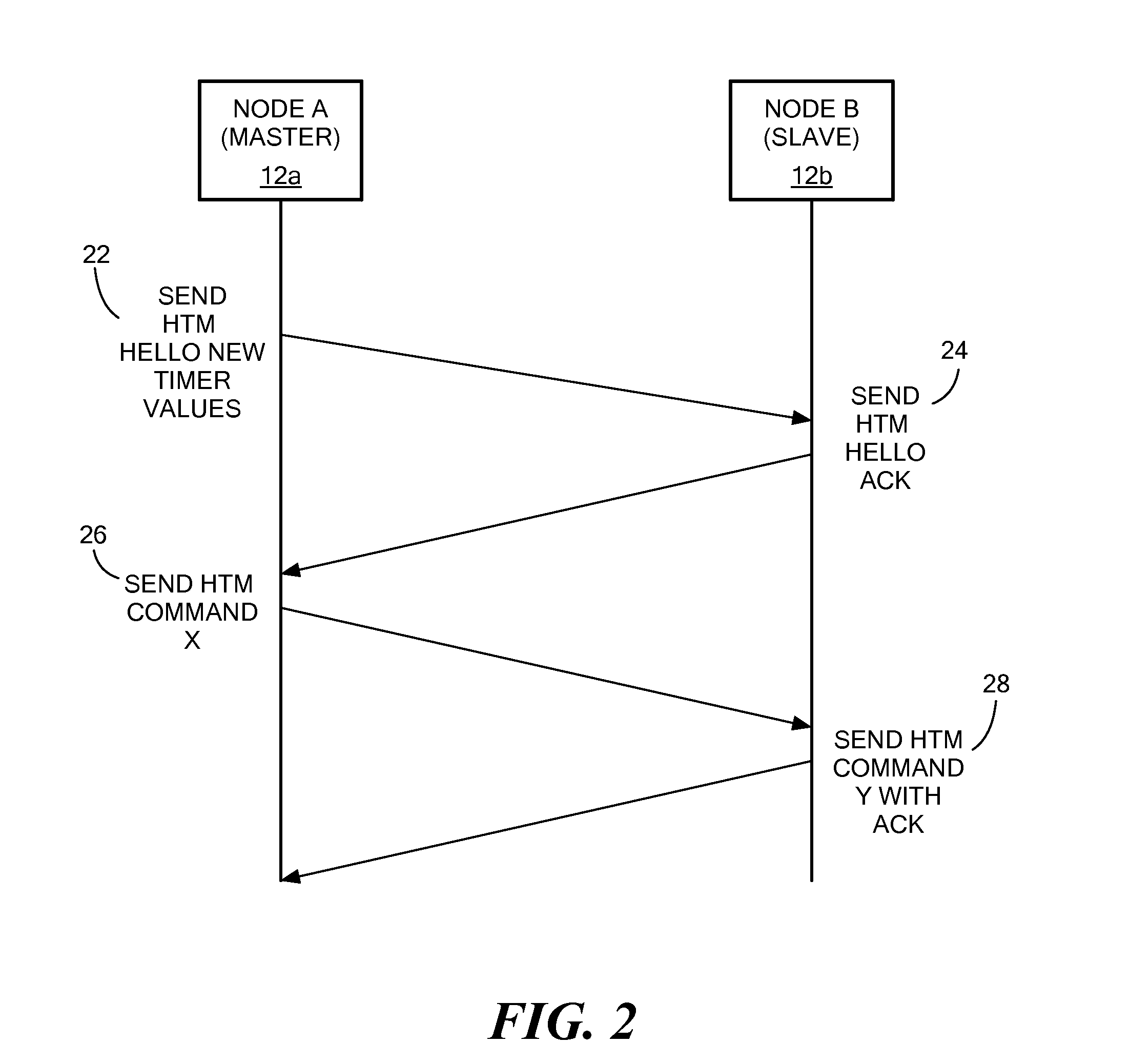
[0016]Before describing in detail exemplary embodiments that are in accordance with the present invention, it is noted that the embodiments reside primarily in combinations of apparatus components and processing steps related to implementing a system and method for determining timer values for an HTM state machine. Accordingly, the system and method components have been represented where appropriate by conventional symbols in the drawings, showing only those specific details that are pertinent to understanding the embodiments of the present invention so as not to obscure the disclosure with details that will be readily apparent to those of ordinary skill in the art having the benefit of the description herein.

[0017]As used herein, relational terms, such as “first” and “second,”“top” and “bottom,” and the like, may be used solely to distinguish one entity or element from another entity or element without necessarily requiring or implying any physical or logical relationship or order ...


PUM


Abstract

A method and system for determining timers in an High Level Data Link Control (HDLC) Traffic Manager (HTM) state machine are disclosed. According to one aspect, the invention provides for determining a transit delay between two nodes by sending a first packet having a delay measurement byte to a second node that is on a link between the first node and the second node. The method also includes receiving a second packet with the delay measurement byte from the second node. The delay measurement byte sent by the second node is adjusted by the second node to indicate its receipt by the second node. A measured delay value is determined. The measured delay value is the delay between a time of sending the first packet to the second node and receiving the second packet from the second node. The measured delay value is determined by the hardware of the first node. Upon determining the measured delay value, timer values of the HTM state machine are set based on the measured delay value.

Description

CROSS-REFERENCE TO RELATED APPLICATION[0001]n / aSTATEMENT REGARDING FEDERALLY SPONSORED RESEARCH OR DEVELOPMENT[0002]n / aFIELD OF THE INVENTION[0003]The present invention relates to communication networks, and more particularly to a method and system for determining timer values for synchronization between a master node and a slave node in a communication network.BACKGROUND OF THE INVENTION[0004]In Automatically Switched Optical Networks (ASON) and Generic Multi-Protocol Label Switching (GMPLS) networks, in-band control plane communication is used for routing and signaling. The integrity of the in-band communication channel is often dependent on the state of the routed circuit that carries the in-band communication control signal. This is true, for example, in the case of a G.709 compliant Optical Data Unit (ODUk) circuit that uses the General Communication Channel (GCC). In this case, the GCC is part of the ODUk / Optical Transport Unit (OTUk) frame and can derive its timing from the O...

Claims


Application Information

Patent Timeline
IPC IPC(8): H04B10/08
CPCH04J3/065H04J3/0667H04J2203/0085H04L43/0858H04L69/28
Inventor MADRAHALLI, VAGISHMOYNIHAN, JEFFREY SCOTTCONKLIN, RICHARDCONNOLLY, MATT
Owner CIENA
Learn More