Electromagnetic solenoid
a solenoid and electromagnet technology, applied in the direction of motor starters, contact mechanisms, magnets, etc., can solve the problems of unstable operation voltage, difficult to attract the movable iron core to the fixed iron core by using the operational voltage, and thereby unstable operation of the movable iron cor
- Summary
- Abstract
- Description
- Claims
- Application Information
AI Technical Summary
Benefits of technology
Problems solved by technology
Method used
Image
Examples
first exemplary embodiment
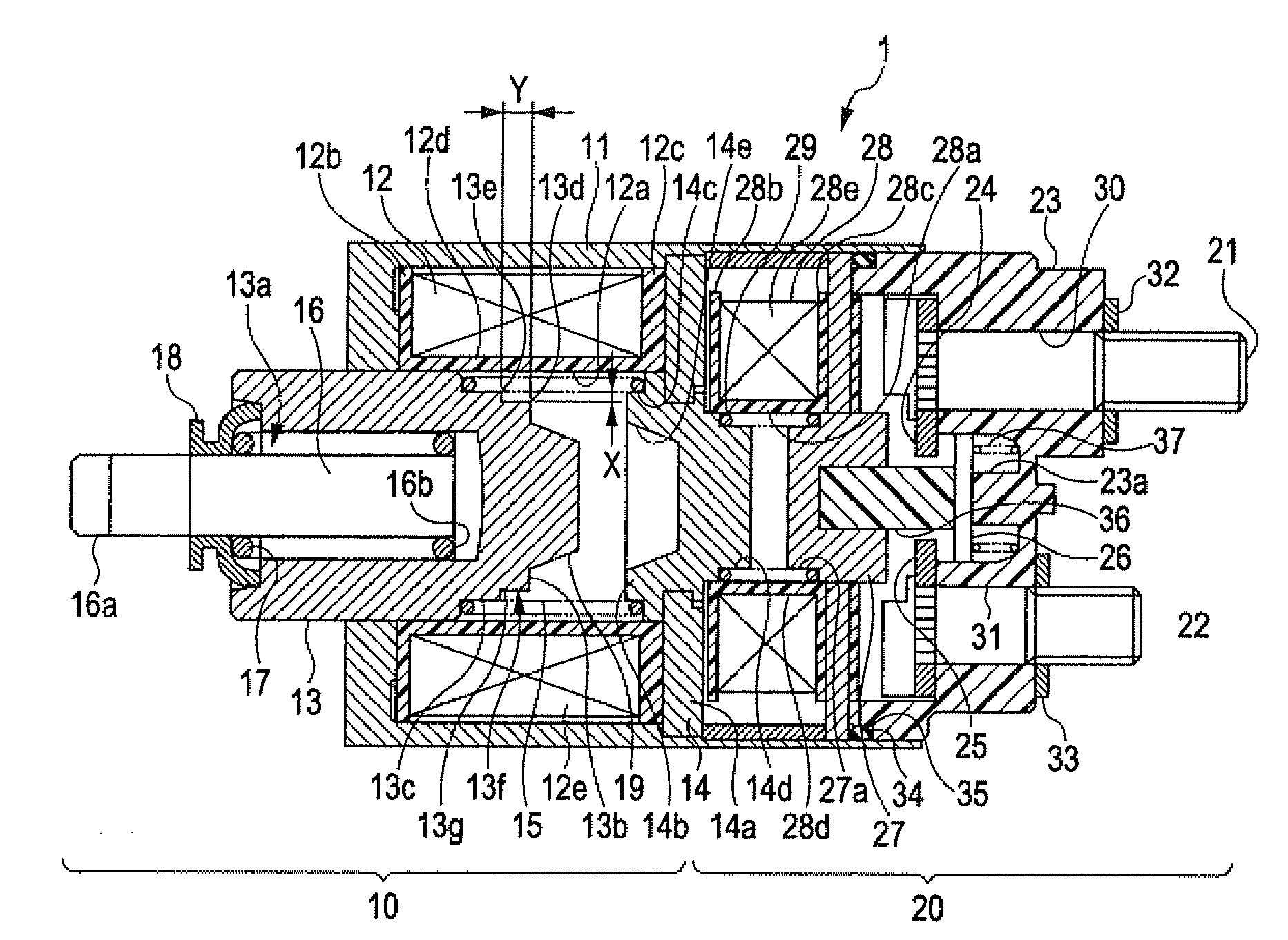
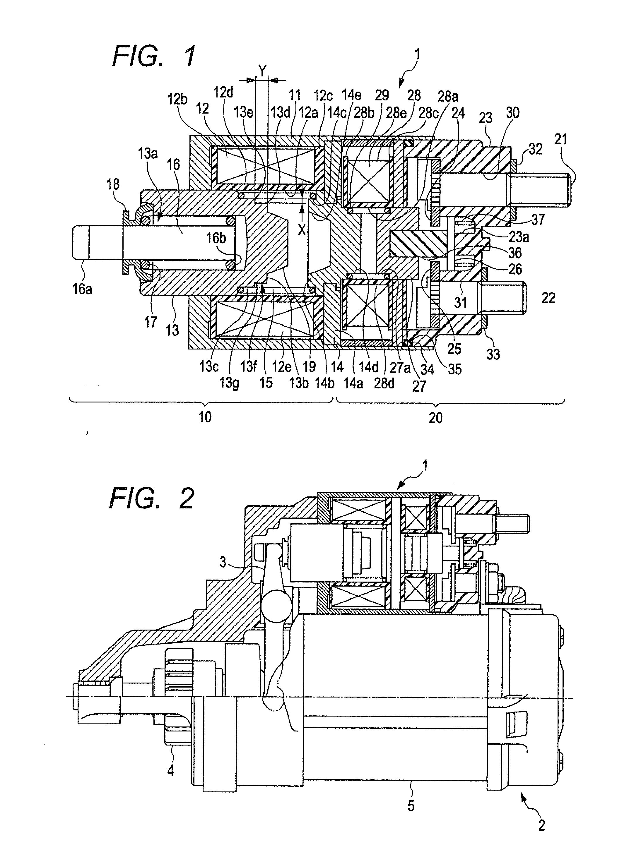
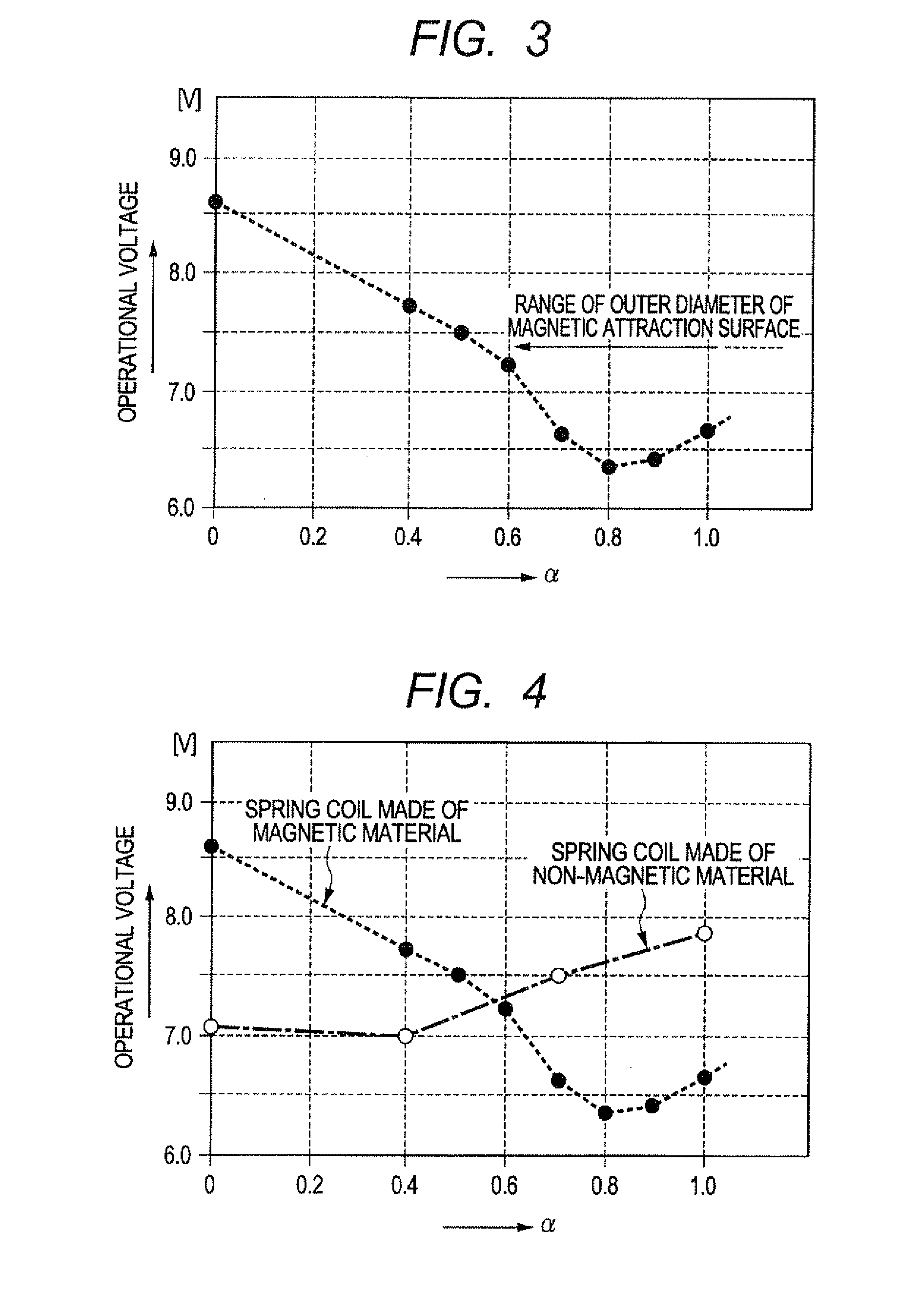
[0036]A description will be given of an electromagnetic solenoid 10 according to a first exemplary embodiment of the present invention with reference to FIG. 1 to FIG. 4.
[0037]The first exemplary embodiment applies the electromagnetic solenoid 10 to a starter device which starts the internal combustion engine mounted to a motor vehicle, for example. In the following description, the direction toward the right side in each diagram indicates the direction toward the starter motor, and the direction toward the left side in each diagram indicates the direction toward the pinion gear.
[0038]FIG. 1 is a view showing a cross section of the electromagnetic switch 1 equipped with the electromagnetic solenoid 10 and the electromagnetic relay 20 according to the first exemplary embodiment of the present invention. FIG. 2 is a view showing a cross section of a starter device equipped with the electromagnetic switch 1 having the electromagnetic solenoid 10 according to the first exemplary embodim...
second exemplary embodiment
[0093]A description will be given of the electromagnetic switch 1-1 equipped with the electromagnetic solenoid 10-1 and the electromagnetic relay 20 with reference to FIG. 5.
[0094]FIG. 5 is a view showing a cross section of the electromagnetic switch 1-1 equipped with the electromagnetic solenoid 10-1 and the electromagnetic relay 20 according to the second exemplary embodiment of the present invention.
[0095]In the structure of the electromagnetic switch 1-1 equipped with the electromagnetic solenoid 10-1 according to the first exemplary embodiment shown in FIG. 1, the small-diameter part 13f is formed between the magnetic attraction surface 13b and the side part of the fitting part 13c which faces the fixed iron core 14. The small-diameter part 13f is smaller in diameter than the fitting part 13c. Further, the decreased-diameter surface 13g (or the decreased-diameter part) is formed approximately in parallel to the movable axis of the movable iron core 13 of the electromagnetic sol...
third exemplary embodiment
[0099]A description will be given of the electromagnetic switch equipped with the electromagnetic solenoid and the electromagnetic relay with reference to FIG. 6.
[0100]FIG. 6 is a view showing a cross section of the electromagnetic switch 1-2 equipped with the electromagnetic solenoid 10-2 and the electromagnetic relay 20 according to the third exemplary embodiment of the present invention.
[0101]In the structure of the electromagnetic switch 1-2 equipped with the electromagnetic solenoid 10-2 and the electromagnetic relay 20 according to the first and second exemplary embodiments, the magnetic attraction surface 13b of the movable iron core 13 of the electromagnetic solenoid 10-2 has the projection part 19 having a tapered shape which projects toward the fixed iron core 14 along the axial direction.
[0102]On the other hand, the third exemplary embodiment shows the magnetic attraction surface 13b-1 without a projection part. Other components of the second exemplary embodiment are the ...
PUM
 Abstract
Description
Claims
Application Information
 - R&D
- Intellectual Property
- Life Sciences
- Materials
- Tech Scout
- Unparalleled Data Quality
- Higher Quality Content
- 60% Fewer Hallucinations
Browse by: Latest US Patents, China's latest patents, Technical Efficacy Thesaurus, Application Domain, Technology Topic, Popular Technical Reports.
© 2025 PatSnap. All rights reserved.Legal|Privacy policy|Modern Slavery Act Transparency Statement|Sitemap|About US| Contact US: help@patsnap.com


