
Synthesizer having adjustable, stable and reproducible phase and frequency

a phase and frequency technology, applied in the direction of measurement devices, pulse automatic control, instruments, etc., can solve the problems of phase relationship loss, precise frequency ratio and exact phase ratio no longer provided, and particularly significant problems, so as to achieve accurate output signals and low cost. , the effect of low cos

Active Publication Date: 2012-05-03
ROHDE & SCHWARZ GMBH & CO KG
View PDF1 Cites 12 Cited by
  • Summary
  • Abstract
  • Description
  • Claims
  • Application Information

AI Technical Summary

Benefits of technology

[0009]Embodiments of the present invention provide a measuring device and a method of operation of a measuring device which allow an exact adjustment of the frequencies and the phase relationship of at least two high-frequency signals with a fast measurement speed.
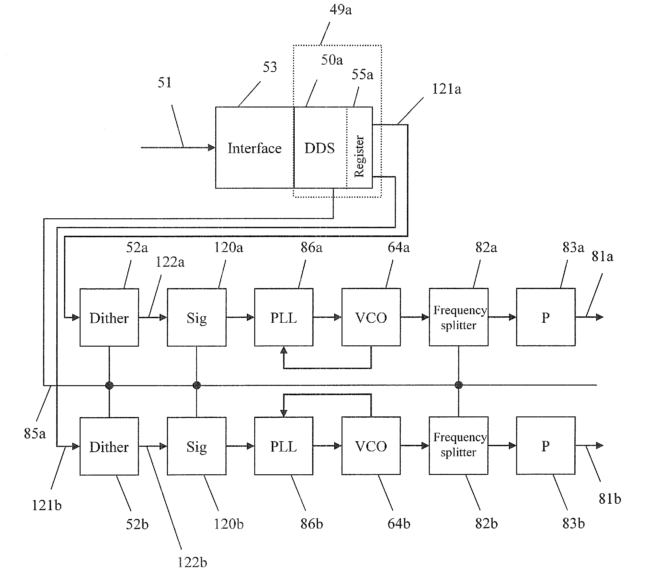
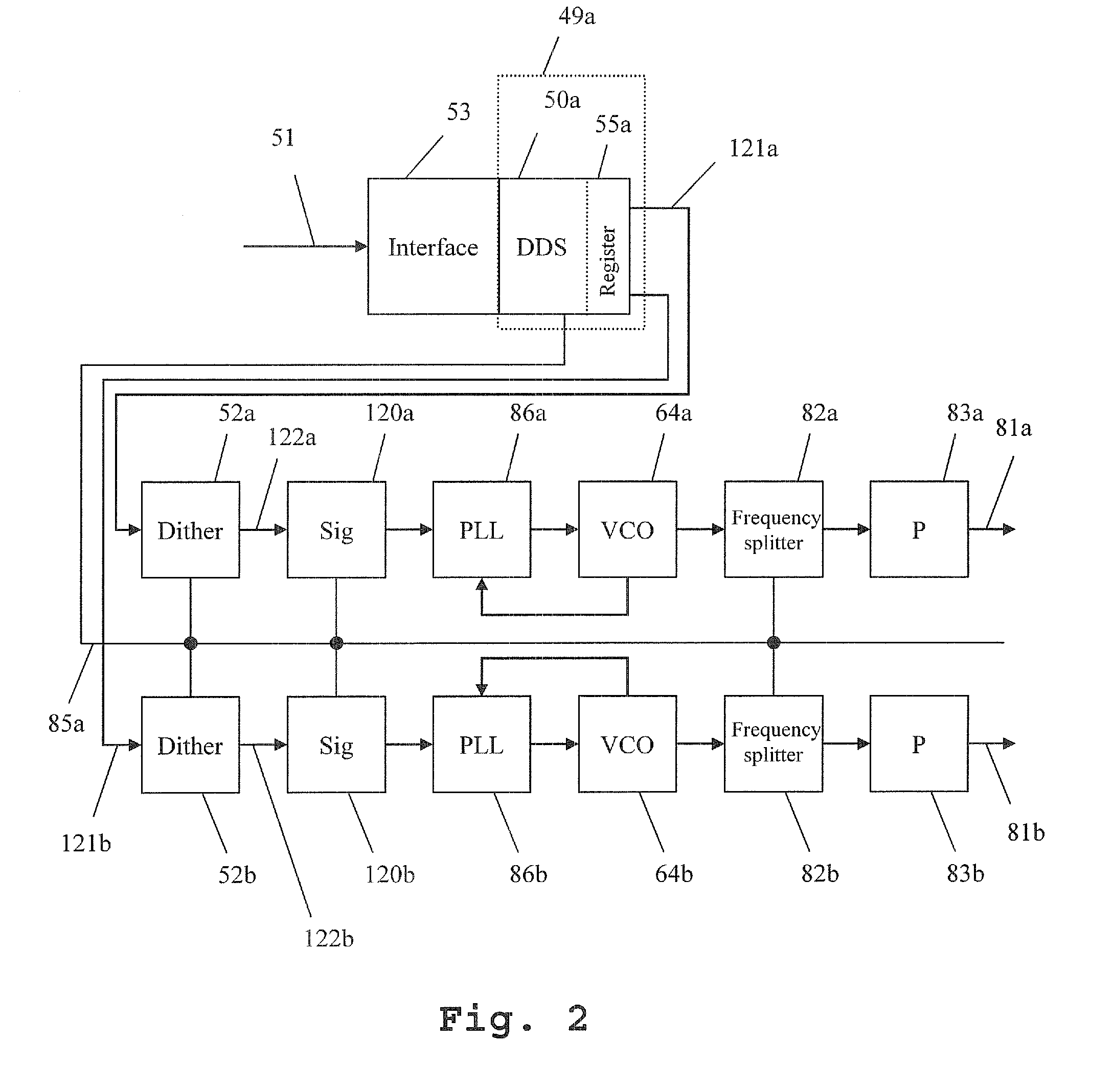
[0010]The measuring device according to embodiments of the invention provides a synthesizer device, at least two controlling devices and at least two controlled oscillators. The synthesizer device contains at least one direct digital synthesizer and generates at least two signals of known phase ratio. Signals generated by the synthesizer device form reference signals of at least one controlling device. Signals formed by the controlling devices control the controlled oscillators. The measuring device contains only frequency splitters, which divide by integer division factors. In this manner, a known phase ratio of the output signals is reliably achieved.
[0011]The synthesizer device preferably contains precisely one direct digital synthesizer and preferably generates at least two signals of identical frequency. In this manner, two signals of identical frequency but different phase position can be generated with minimum cost, as required for differential signal pairs with 180° phase difference.

Problems solved by technology

The problem becomes particularly significant if a plurality of signal generators is involved, for example, in the case of differential multi-port measurements, or complex conversion measurements on frequency-converting devices under test, for example, mixers.
However, an exact frequency ratio and an exact phase ratio are then no longer provided.
However, the phase relationship is lost via the fractional splitting.
However, this is very slow and requires a large volume of software.
This results in a slow measurement speed.

Method used


Image

  • Synthesizer having adjustable, stable and reproducible phase and frequency
  • Synthesizer having adjustable, stable and reproducible phase and frequency
  • Synthesizer having adjustable, stable and reproducible phase and frequency

Examples


Embodiment Construction

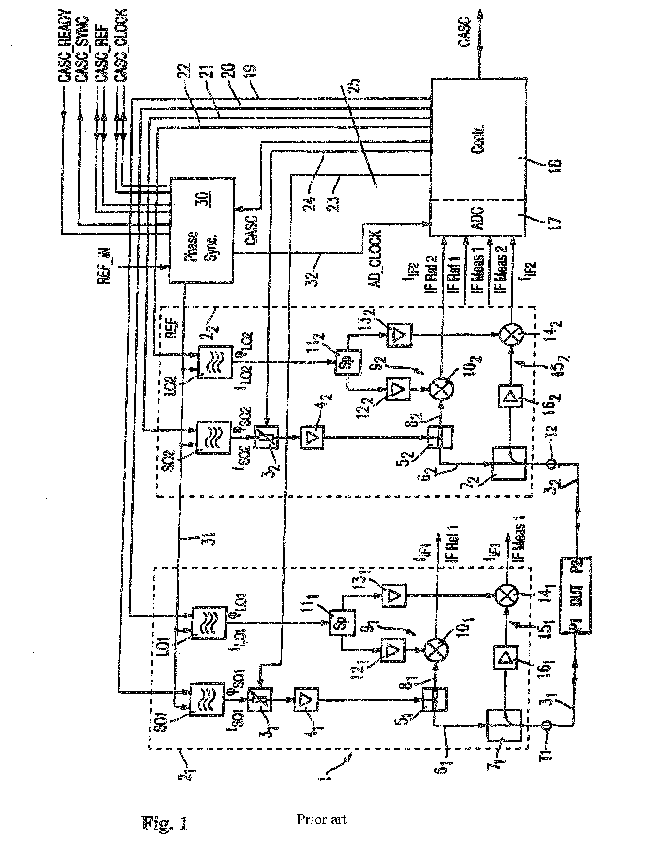
[0026]The problem underlying the present invention is first explained with reference to FIG. 1. The structure and method of operation of various exemplary embodiments of the measuring device according to the invention are then shown with reference to FIGS. 2-4. Finally, the operation of an exemplary embodiment of the method according to the invention is shown with reference to FIG. 5.

[0027]The presentation and description of identical elements in similar drawings has not been repeated in some cases.

[0028]FIG. 1 shows an example of a measuring device. This is a 2-port vectorial network analyzer.

[0029]In the illustrated network analyzer, a separate excitation / reception unit 21 or respectively 22 is present at each port T1, T2 of the network analyzer. Each excitation / reception unit 21 or respectively 22 provides a signal generator SO1 or respectively SO2, with which the device under test DUT can be supplied with an excitation signal. Either only one of the two signal generators SO1 or ...


PUM


Abstract

A measuring device provides a synthesizer device, at least two controlling devices and at least two controlled oscillators. The synthesizer device contains at least one direct digital synthesizer and generates at least two signals of known phase ratio. Signals generated by the synthesizer device form reference signals of at least one controlling device. Signals formed by the controlling devices control the controlled oscillators. The measuring device contains only frequency splitters, which divide by integer division factors.

Description

CROSS-REFERENCE TO RELATED APPLICATION[0001]The present application is a national phase application of PCT Application No. PCT / EP2010 / 000809, filed on Feb. 10, 2010, and claims priority to German Patent Application No. DE 10 2009 011 795.4, filed on Mar. 5, 2009, the entire contents of which are herein incorporated by reference.BACKGROUND OF THE INVENTION[0002]1. Field of the Invention[0003]The invention relates to a measuring device with signal generators with adjustable, stable and reproducible phases and frequencies and a method for the operation of a measuring device for generating signals with adjustable, stable and reproducible phases and frequencies.[0004]2. Discussion of the Background[0005]In metrology, for example, in network-analysis metrology, a high-frequency signal is used to supply the device under test. A further high-frequency signal is used as a local oscillator signal in order to mix the received generator signals into an appropriate intermediate frequency positio...

Claims


Application Information

Patent Timeline
Patent Type & Authority Applications(United States)
IPC IPC(8): G01R23/02
CPCG01R27/28H03L7/23H03L7/18G01R31/2841
Inventor ORTLER, GEORGEVERS, CHRISTIANFREIDHOF, MARKUS
Owner ROHDE & SCHWARZ GMBH & CO KG
Learn More