
Magnetic flux concentrator for increasing the efficiency of an electromagnetic pickup

a technology of electromagnetic pickups and flux concentrators, which is applied in the field of electromagnetic pickups, can solve the problems that the idea of incorporating a device that reduces the strength or concentration of the magnetic field emanating from the pickups to achieve the effect of reducing the magnetic energy available to strings

Active Publication Date: 2012-05-03
KINMAN CHRISTOPHER
View PDF10 Cites 26 Cited by
  • Summary
  • Abstract
  • Description
  • Claims
  • Application Information

AI Technical Summary

Benefits of technology

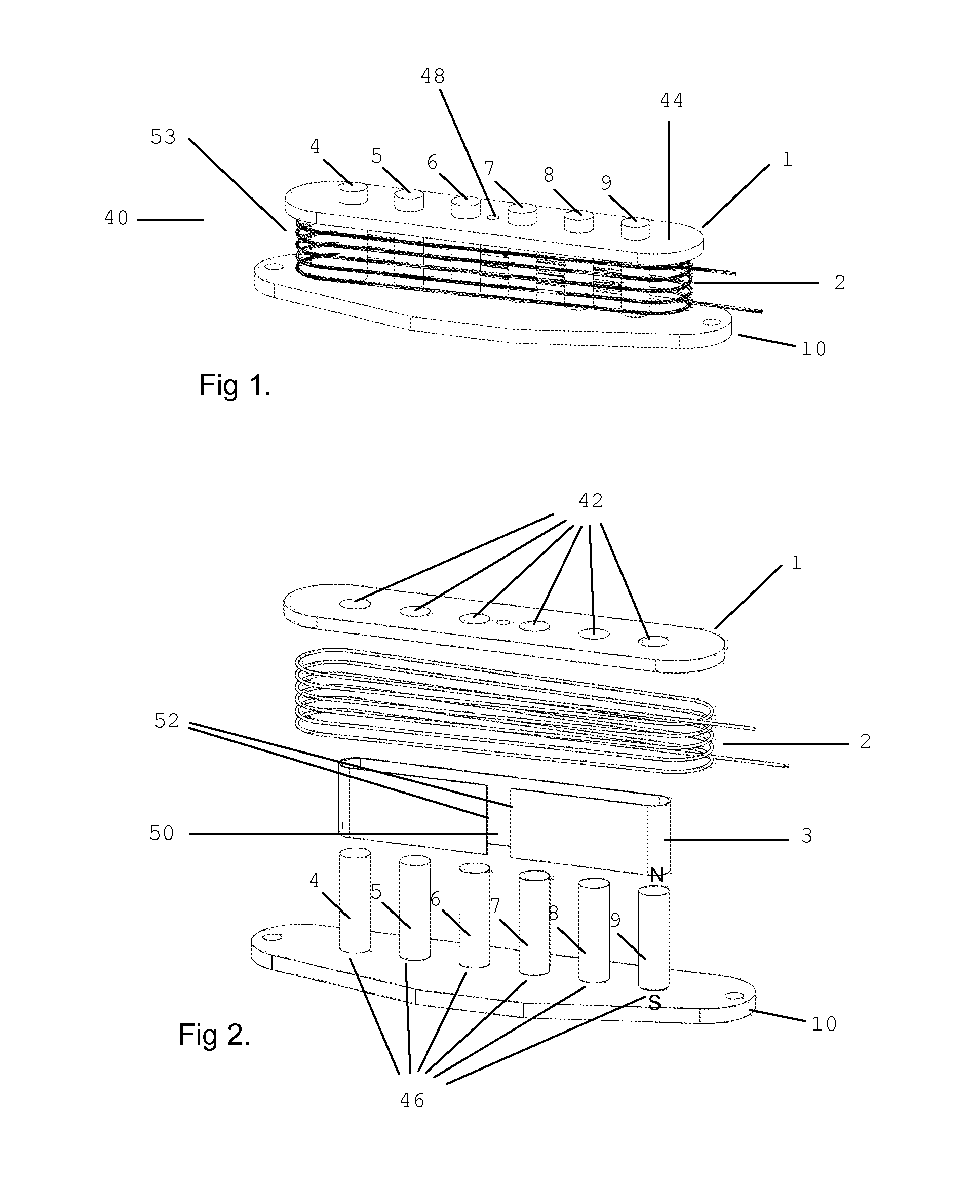
[0012]The inventive magnetic flux concentrator device may be comprised of one or more metal strips of magnetic material or magnetic wire, for example fine steel wire, disposed within the sensing coil. The inclusion of a magnetic material within the sensing coil attracts and concentrates a substantially greater amount of available magnetic energy into the coil space as compared to prior art designs. By attracting available magnetic energy from the ends of the magnetized coil core, which, in one embodiment, it surrounds, the inventive magnetic flux concentrator device tends to have the effect of reducing the magnetic energy available to the strings at the ends of the magnetized core. This may be thought of as short circuiting available magnetic energy.

Problems solved by technology

Thus, the notion of incorporating a device that reduces the strength or concentration of the magnetic field emanating from a pickup hitherto might have been dismissed as self defeating and has not previously been practiced in the art.

Method used


Image

  • Magnetic flux concentrator for increasing the efficiency of an electromagnetic pickup
  • Magnetic flux concentrator for increasing the efficiency of an electromagnetic pickup
  • Magnetic flux concentrator for increasing the efficiency of an electromagnetic pickup

Examples


Embodiment Construction

[0036]Essentially all electromagnetic pickups have a ferromagnetic core associated with a coil of insulated copper wire. The core may be permanent rod magnets, iron rods in the form of adjustable steel screws, non-adjustable iron rods, a combination of both steel screws and iron rods, or a singular iron bar known as a blade or rail.

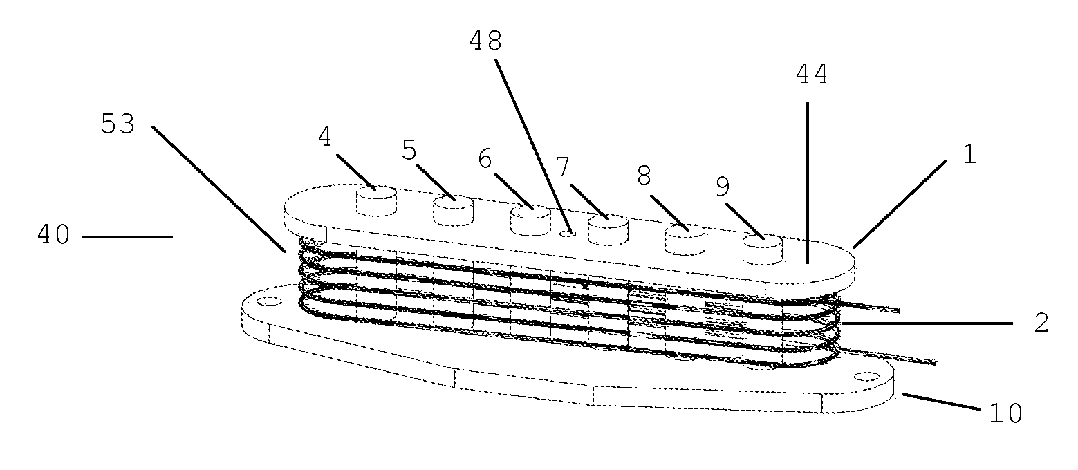
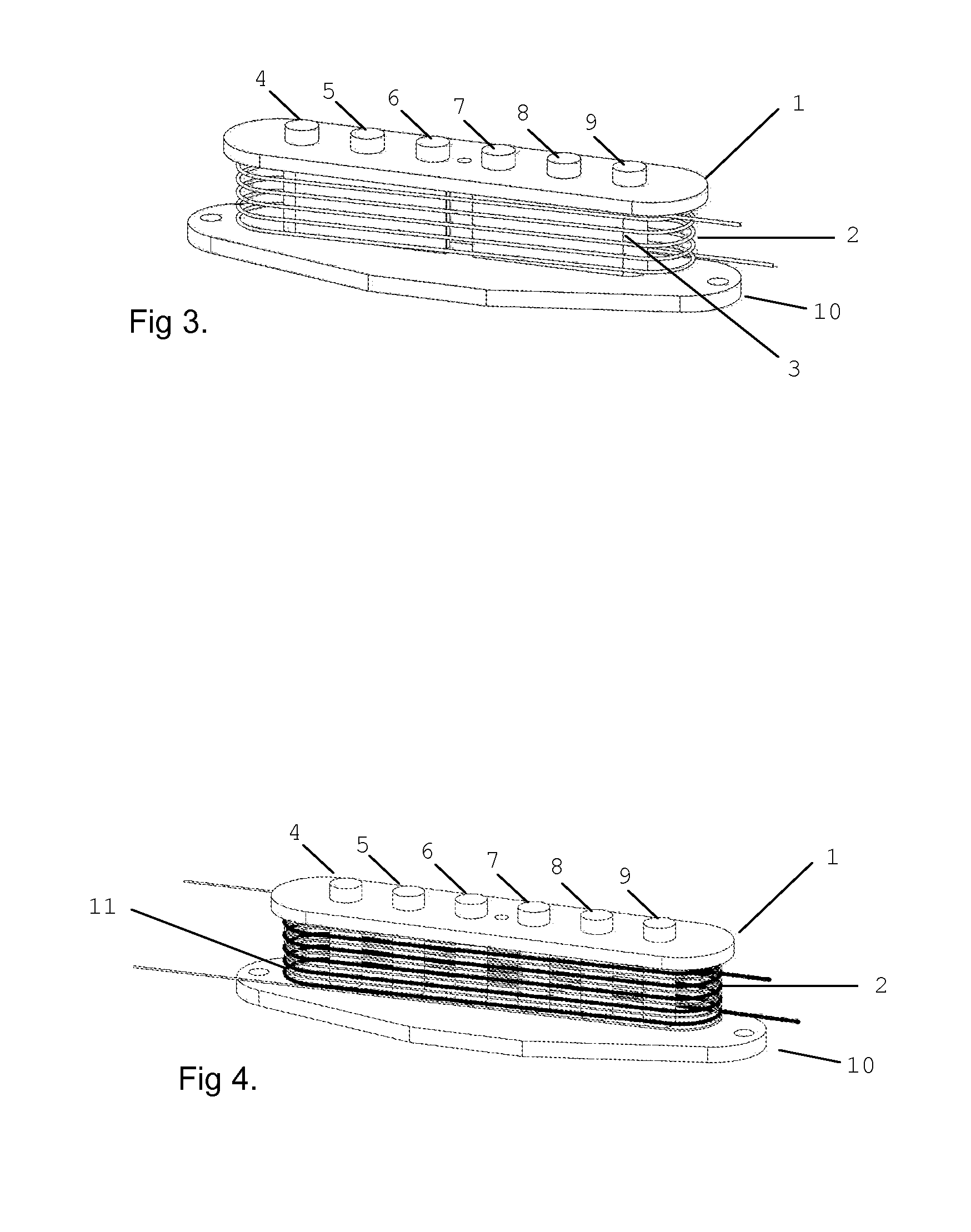
[0037]One embodiment of a pickup incorporating the inventive magnetic flux concentrator device, which is shown in FIGS. 1, 2 and 3, uses a plurality of Alnico rod magnets 4, 5, 6, 7, 8, and 9 to form a core. A coil 2 is wound around Alnico rod magnets 4, 5, 6, 7, 8, and 9. Coil 2 is comprised of many turns of insulated copper wire, for example, 8000 turns of 42 gauge varnished or otherwise insulated copper wire or the equivalent. Rod magnets 4-9 have a diameter of 4.8 mm and a length of 17 mm, and have been permanently magnetized to a degree typical of rod magnets in guitar pickups. Rod magnets 4, 5, 6, 7, 8, and 9 may be obtained from AZ Industries, Inc....


PUM


Abstract

An electromagnetic pickup adapted to be secured to a stringed musical instrument, such as a guitar or bass or the like, of the type having a plurality of magnetic strings of ferromagnetic composition such as steel tensioned to provide musical notes under mechanical stimulation such as picking is disclosed. The electromagnetic pickup comprises at least one magnetized core having a length and a width. An electrically conductive material is wound into at least one coil around the magnetized core, and a ferromagnetic material such as iron, nickel, cobalt or alloys thereof is positioned on at least one side of the length and internally of at least a portion of the electrically conductive material. The electromagnetic pickup is mounted proximate the strings in such a manner that magnetic field of the pickup extends to the strings for the purpose of generating an output electrical signal analogous to the musical notes.

Description

CROSS REFERENCE TO RELATED APPLICATIONS[0001]This application claims the benefit of U.S. Provisional Patent Application No. 61 / 407,149, filed Oct. 27, 2010, the disclosure of which is hereby incorporated herein by reference thereto.TECHNICAL FIELD[0002]The present invention relates to electromagnetic pickups for amplified stringed musical instruments such as a guitar and, more particularly, to an electromagnetic pickup having a magnetic field which is significantly more concentrated internally than those of existing magnetic pickups for the purpose of improved efficiencies.STATEMENT REGARDING FEDERALLY SPONSORED RESEARCH OR DEVELOPMENT[0003](Not applicable)BACKGROUND OF THE INVENTION[0004]Electromagnetic pickups are used in amplified stringed musical instruments, one example being electric guitars, for the purpose of deriving an electrical signal from vibration of the guitar's strings. This electrical signal is fed to an amplifier and subsequently to a loudspeaker system for convers...

Claims


Application Information

Patent Timeline
IPC IPC(8): G10H3/18
CPCG10H3/181G10H2220/515G10H2220/511
Inventor KINMAN, CHRISTOPHER
Owner KINMAN CHRISTOPHER
Learn More