
Mobile communication system, terminal device, and base station

a mobile communication system and terminal device technology, applied in the field of mobile communication systems, can solve the problems of long insufficient transmission of report (including only the pci) to the network only once, and insufficient mme for access control, so as to reduce the wait time for handover control

Inactive Publication Date: 2012-04-26
PANASONIC CORP
View PDF1 Cites 45 Cited by
  • Summary
  • Abstract
  • Description
  • Claims
  • Application Information

AI Technical Summary

Benefits of technology

[0012]The present invention has been made against the background described above. An object of the present invention consists in providing a mobile communication system that enables avoiding the occurrence of a service interruption and reducing the wait time for handover control.Solution To Problem
[0014]In the present invention, the physical cell ID deployment map information including at least the information indicating the correspondences between the physical cell IDs and the unique cell IDs is used to generate the measurement result report. Therefore, even if two or more small cells having the same physical ID exist within a macrocell, an accessible small cell can be identified from the unique cell ID. This enables avoiding a service interruption caused by performing handover control to an inaccessible small cell and ending in a handover failure. Also, the need of the conventionally-required second measurement result report is eliminated, which enables a reduction in the wait time for handover control.

Problems solved by technology

In such a case, transmitting the report (including only the PCI) from the mobile terminal to the network only once is insufficient for the MME to perform access control.
A second measurement result report including information such as a unique cell ID (a CGI) that allows uniquely identifying the CSG cell is required, leading to a long wait time for handover control.
However, the above approach of using the fingerprint information has some limitations.
By way of example, the mobile terminal is not necessarily able to use accurate history information: the history information may become outdated, for example.
The mobile terminal is not always able to use position information: GPS information becomes inaccurate particularly in indoor or underground use, for example.
In consideration of these limitations, the approach of using the fingerprint information may let the mobile terminal make an incorrect cell determination due to incorrect cell position information.
If a handover is controlled based on the incorrect cell determination (e.g., if a handover is incorrectly controlled to a cell for which access is actually not granted), the handover process may fail and result in an interruption of a service that the mobile terminal has been receiving.
However, as mentioned above, the terminal device may not always be able to use the position information.
However, since it takes long time to obtain the CGI (compared to the PCI), transmitting the first report is delayed.
This increases the delay time for the mobile terminal to transmit the measurement result report.

Method used


Image

  • Mobile communication system, terminal device, and base station
  • Mobile communication system, terminal device, and base station
  • Mobile communication system, terminal device, and base station

Examples


first embodiment

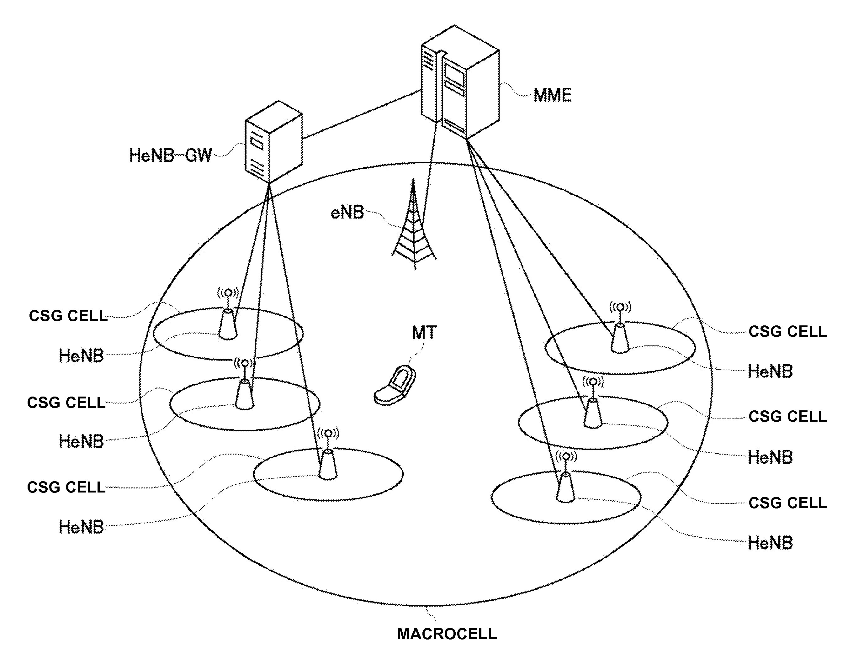
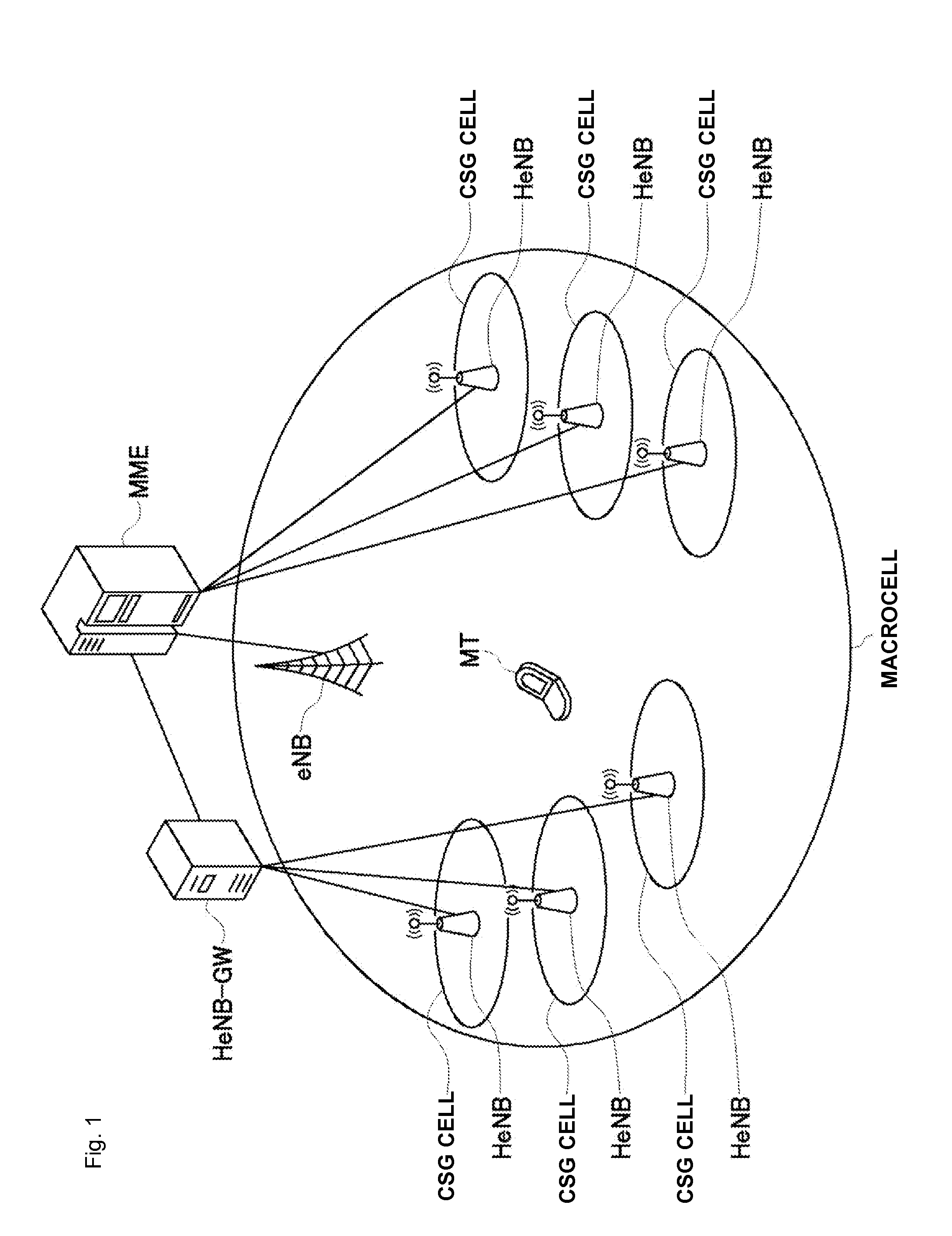
[0032]A configuration of a mobile communication system in a first embodiment of the present invention will be described with reference to the drawings. FIG. 1 is an illustrative diagram schematically showing the configuration of the mobile communication system in this embodiment. As shown in FIG. 1, the mobile communication system includes several CSG cells, each of which is implemented by a home base station (HeNB). Some of the home base stations (HeNBs) are directly connected to a mobility management entity (MME), and the other home base stations (HeNBs) are indirectly connected to the mobility management entity (MME) via a gateway (HeNB-GW). The CSG cells are disposed within the coverage of a base station (eNB) of a macrocell. The macrocell base station (eNB) is also connected to the MME through an interface.

[0033]Here, the eNB corresponds to a macrocell base station of the present invention. The HeNBs correspond to small cell base stations of the present invention, and the CSG c...

second embodiment

[0093]A mobile communication system in a second embodiment of the present invention will be described. Here, the mobile communication system in the second embodiment will be described mainly with respect to what are different from the first embodiment. Accordingly, unless otherwise stated herein, configurations and operations in this embodiment are the same as the first embodiment.

[0094]In the first embodiment, the mobile terminal (MT) simply reports the PCIs and the CGIs when the same PCI values are found in the PDM information. In the system in the second embodiment, different HeNBs within the same macrocell can be given the same PCI value without causing interference with each other. That is, this embodiment can also address a scenario such that different HeNBs having the same PCI value are remotely located within the same macrocell.

[0095]For example, as shown in FIG. 9, two CSG cells within a macrocell may be remotely located while taking the same PCI value (PCI-3). The PCI dete...


PUM


Abstract

In a mobile communication system, a handover of a terminal device (MT) from a macrocell base station (eNB) to a small cell base station (HeNB) is controlled via a host device (MME or HeNB-GW). Physical cell ID deployment map information (PCI deployment map information), which includes at least information (PCI / CGI map information) indicating the correspondences between physical cell IDs and unique cell IDs of CSG cells for which access is granted, is generated in the host device (MME or HeNB-GW). When the terminal device measures the reception quality for surrounding CSG cells for handover control to any of the CSG cells, the terminal device uses the PCI deployment map information to generate a measurement result report. Thus, a service interruption caused by handover control to an inaccessible small cell can be avoided, and the wait time for handover control can be reduced.

Description

TECHNICAL FIELD[0001]The present invention relates to a mobile communication system in which a handover of a terminal device from a macrocell base station to a small cell base station is controlled via a host device.BACKGROUND ART[0002]In a mobile communication system (e.g., based on 3GPP LTE (Long-Term Evolution), a mobile terminal (MT) needs to address handovers from one cell to another. Such handovers include a handover between macrocells, a handover between CSG cells, and a handover between a macrocell and a CSG cell. In a handover from a macrocell to a CSG cell, a base station (eNB) and a home base station (HeNB) do not directly connect with each other, and only a handover (S1 handover) via a core network (also called a mobility management entity (MME)) is possible. In current network configurations, access control for a handover from a macrocell to a CSG cell (also called an inbound handover) is performed by the mobility management entity (MME).[0003]When a handover between ma...

Claims


Application Information

Patent Timeline
IPC IPC(8): H04W36/00
CPCH04W36/04
Inventor ISHIDA, CHIEAOYAMA, TAKAHISATOH, HONG TATCHENG, HONGKOH, TIEN MING BENJAMIN
Owner PANASONIC CORP
Learn More