Mechanical Seal

Active Publication Date: 2012-04-26
VULCO
View PDF17 Cites 7 Cited by
  • Summary
  • Abstract
  • Description
  • Claims
  • Application Information

AI Technical Summary

Benefits of technology

[0007]In one form, the one or more members is placed in tension so as to provide the biasing force. An advantage of this arrangement is that the biasing device can apply a more consistent biasing force over a larger displacement as compared to a spring such as a coil spring which has been commonly used in the past in mechanical seals. Typically a spring force will vary significantly under longitudinal displacement since the elastic constant “K” is relatively high as compared to the elastic constant of the resilient member(s), particularly when those members are arranged to be placed in tension. Having an arrangement where the biasing device can provide a consistent biasing force over a relatively large displacement provides substantial benefit. In particular, the actual biasing force is not dependent on very accurate alignment of the components and any maladjustments or play in the equipment does not significantly affect the biasing force applied. Moreover, as the sealing surfaces wear, the biasing device needs to adapt to move the sealing face to accommodate the wear so as to maintain the sealing faces in contact. The biasing device according to at least one form above is able to provide a more consistent biasing force over larger wear ranges than previous mechanical seals using coil spring arrangements.
[0008]In a particular form, the biasing device is arranged to apply a substantially uniform biasing force to the sealing face disposed on the support assembly so as to assist in maintaining alignment of the contacting sealing faces.
[0014]In particular form, the support assembly forms part of a fluid barrier of the seal and the biasing device is fluid impervious and forms part of that barrier. An advantage of the biasing device having the dual function of imparting a biasing force to the sealing face and forming part of a fluid barrier of the mechanical seal is that the number of components in the mechanical seal can be reduced. In previous mechanical seals that incorporated coil springs, the springs need to be isolated where possible from the fluid and as such the mechanical seal required additional sealing arrangements to isolate the springs and provide the fluid barrier between the rotary and stationary parts.

Problems solved by technology

Moreover, as the sealing surfaces wear, the biasing device needs to adapt to move the sealing face to accommodate the wear so as to maintain the sealing faces in contact.

Method used


Image

  • Mechanical Seal
  • Mechanical Seal
  • Mechanical Seal

Examples


Embodiment Construction

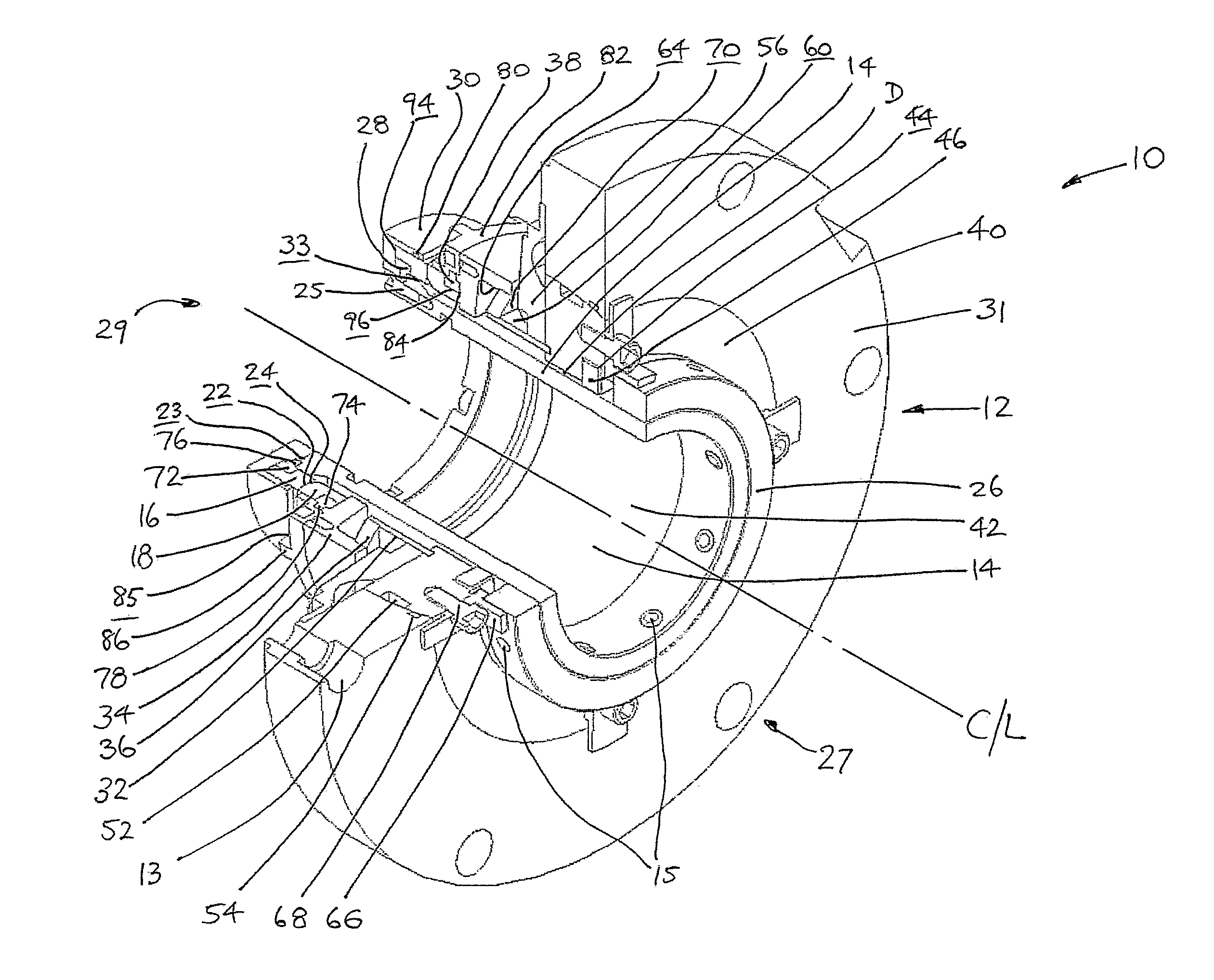
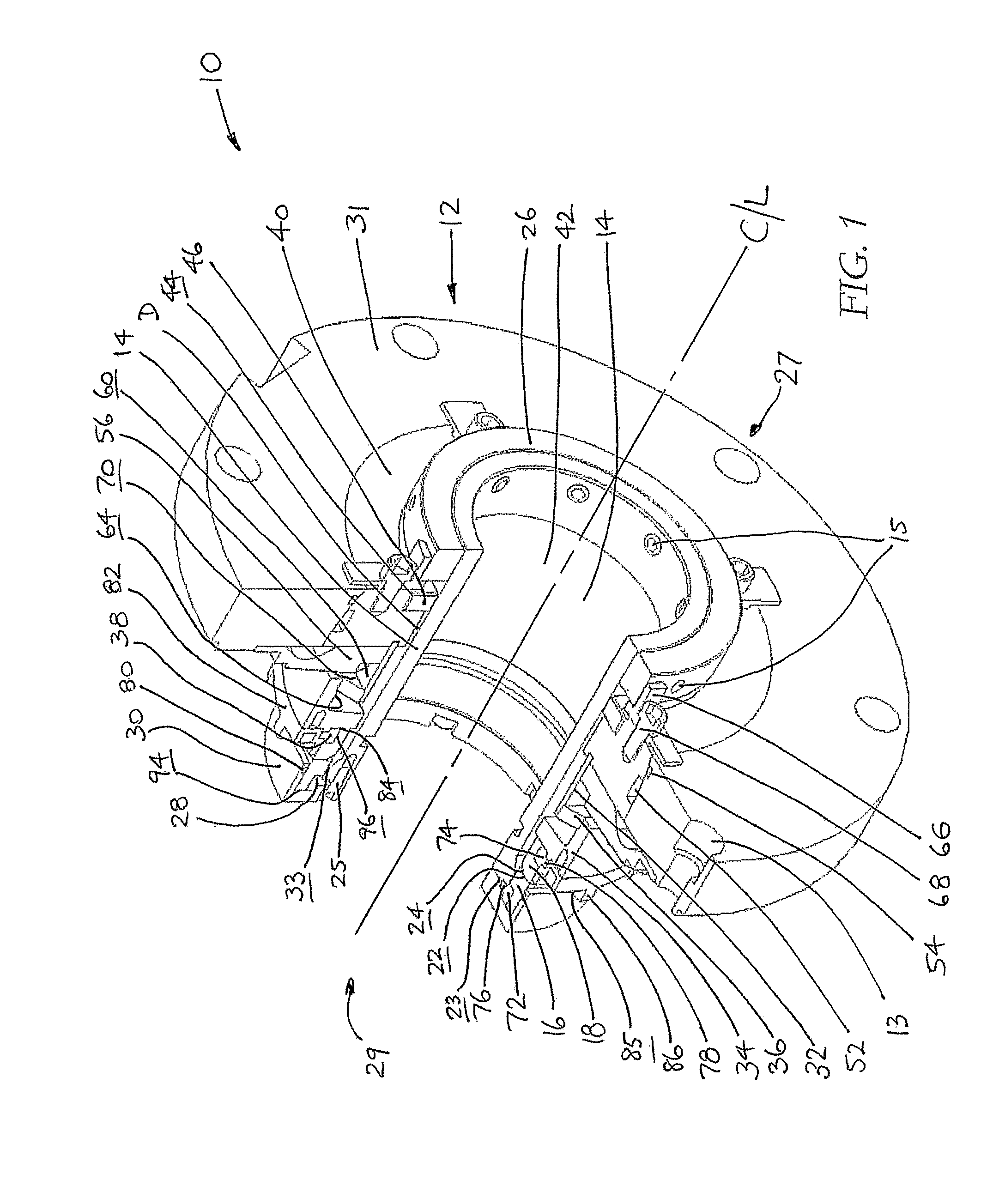
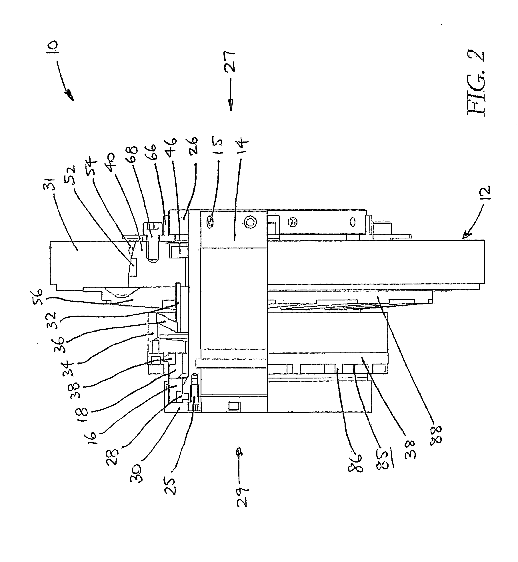
[0030]Turning to the drawings, in FIG. 1 a mechanical seal 10 is disclosed which is for use in providing a sealing interface between rotary and stationary components. Broadly, the mechanical seal 10 includes a stationary part or housing 12 in the form of a generally annular-shaped flange or ring 31 and a rotatable part which is generally in the form of a shaft sleeve 14 which extends through the housing 12 and is rotatable about an axis CL. There are various components which connect the rotatable and stationary parts, which will now be described.

[0031]To form a fluid seal between the stationary annular flange 31 and the rotatable shaft sleeve 14, a pair of sealing members in the form of continuous rings 16, 18 are provided. In use, the rings 16, 18 are mounted on respective support structures of the seal 10. In the embodiment as shown, one of the sealing rings 16 rotates and is affixed to the shaft sleeve 14, whereas the other sealing ring 18 remains stationary by being fitted to th...


PUM


Abstract

A mechanical seal is disclosed having a rotatable sealing face and a stationary sealing face that are in opposed relation and arranged to be urged, into contact to form a seal. One of the sealing faces is mounted on a support assembly that includes a biasing device operative to move that sealing face into contact with the other sealing face. In one form of the invention, the biasing device comprises one or more resilient members that in use are deformed to provide the biasing force. In a second form of the invention, the support assembly forms part of a fluid barrier of the seal and the biasing device is fluid impervious and forms part of the barrier. In a third form of the invention, the biasing device is exposed to fluid pressure in the chamber and the biasing force increases on increasing the fluid pressure in the chamber.

Description

TECHNICAL FIELD[0001]This disclosure relates to a mechanical seal for providing a fluid seal between rotatable and stationary components. The mechanical seal has been developed especially, but not exclusively for use in fluid pumps, such as slurry pumps, where the mechanical seal is mounted between a rotatable drive shaft and a pump casing and is herein described in that context. However, it is to be appreciated that such a mechanical seal can have broader application and is not limited to that use.BACKGROUND ART[0002]Mechanical seals have been used to provide a fluid seal between a rotatable shaft and a fluid containing chamber. As such, mechanical seals have application in pumps where the drive shaft of an externally mounted pump motor extends through a pump casing to drive a pump impeller. In such an application, the mechanical seal is typically situated where the rotatable shaft enters or leaves the casing and is fitted to the casing and the rotatable shaft to provide a seal bet...

Claims


Application Information

Patent Timeline
IPC IPC(8): F04D29/04F16J15/40F16J15/34
CPCF04D29/126F16C17/04F16J15/3404F16J15/344F04D29/12F16J15/3464F16J15/36F16J15/38F16J15/3448F04C27/00F16J15/16F16J15/34F16J15/54F16C2360/44F16J15/3208
Inventor ABARCA MELO, RICARDOGUZMAN CASTRO, RODRIGOQUIROZ VENEGAS, OSVALDO
Owner VULCO
Why Eureka
Try Eureka