
Light emitting diode driving device

a technology of led driving and light emitting diodes, which is applied in the direction of lighting apparatus, electroluminescent light sources, light sources, etc., can solve the problems of cost and size the short operational life of conventional led driving circuits, so as to improve the light emitting efficiency of leds and improve the efficiency of led illuminators. the effect of the entire efficiency

Inactive Publication Date: 2012-04-26
SEOUL SEMICONDUCTOR +1
View PDF7 Cites 29 Cited by
  • Summary
  • Abstract
  • Description
  • Claims
  • Application Information

AI Technical Summary

Benefits of technology

[0009]Exemplary embodiments of the present invention also provide an LED driving device that can control harmonic waves and a power factor and simultaneously prevent the brightness of LEDs from being varied due to changes in input voltage.
[0010]Exemplary embodiments of the present invention also provide an LED driving device that can improve the entire efficiency of an LED illuminator by improving the light emitting efficiency of LEDs.

Problems solved by technology

However, the conventional LED driving circuit may have a problem with cost and size, and also may include an electrolytic capacitor that has a shorter operational lifetime than that of the LEDs.
Even when a smoothing circuit is used in a conventional LED driving circuit, an electrolytic capacitor may also be used, so the shorter operational lifetime may also affect the smoothing circuit.

Method used


Image

  • Light emitting diode driving device
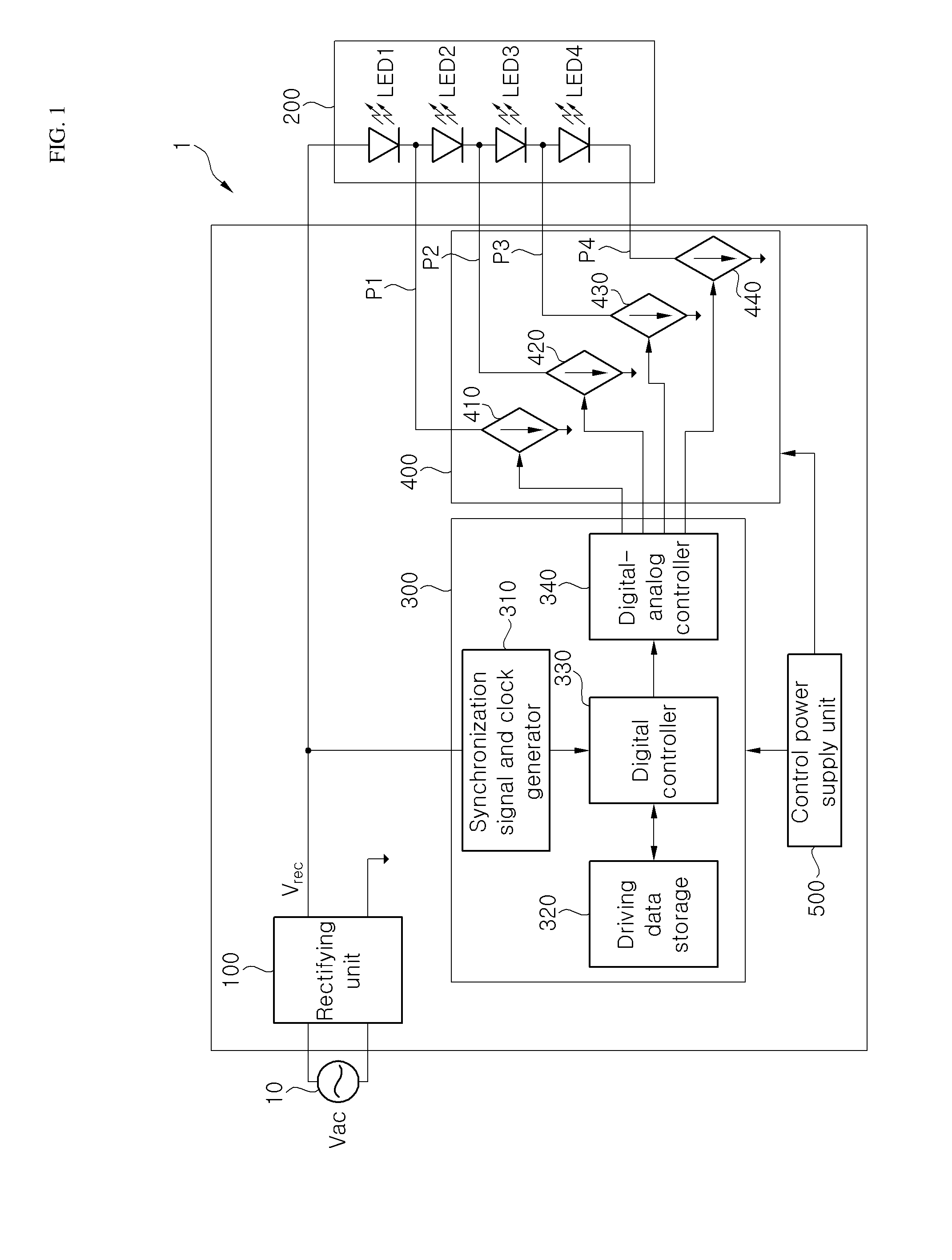
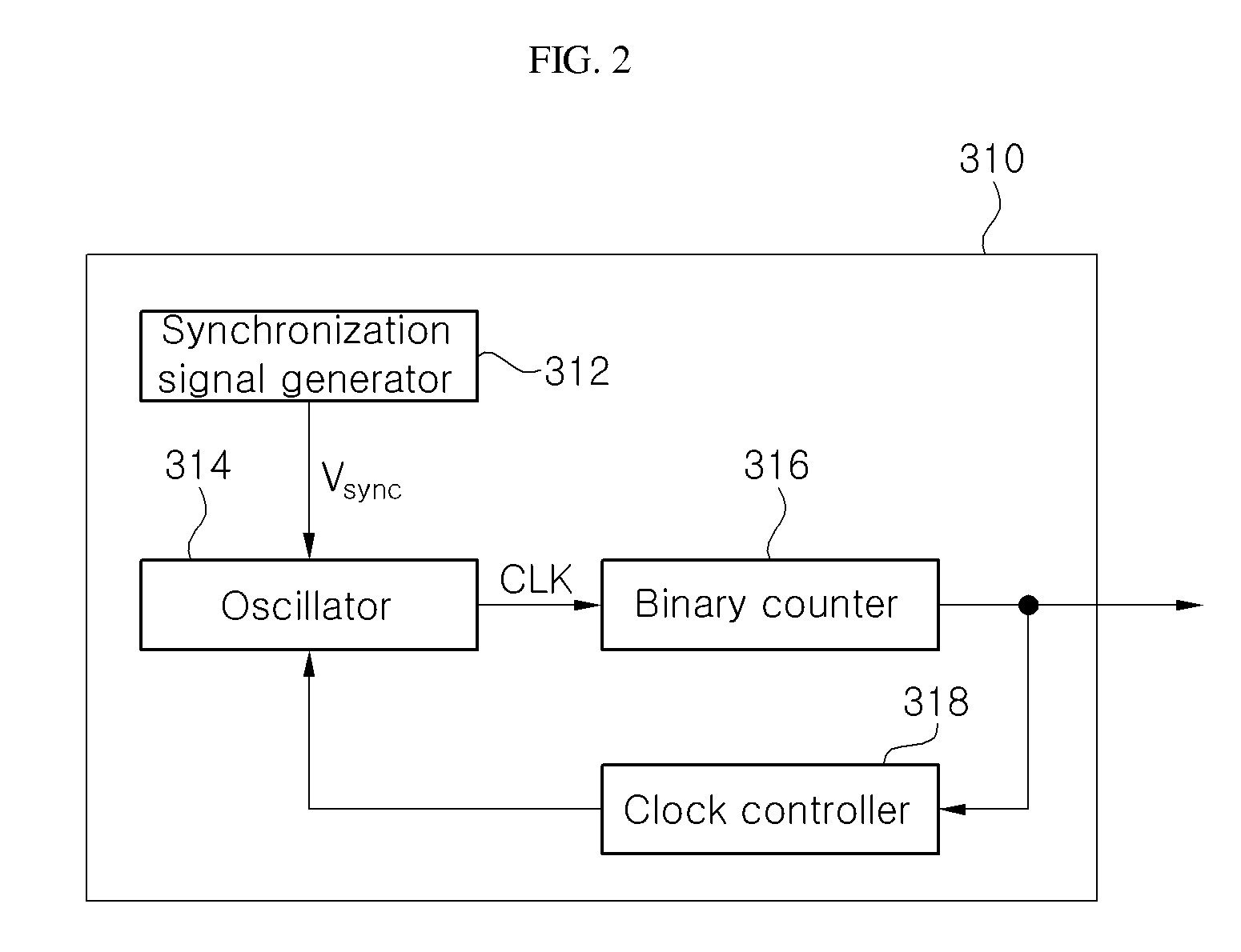
  • Light emitting diode driving device
  • Light emitting diode driving device

Examples


Embodiment Construction

[0025]Hereinafter, exemplary embodiments of the present invention will be described in detail with reference to the accompanying drawings. The following exemplary embodiments are provided only for illustrative purposes so that those skilled in the art can fully understand the spirit of the present invention. Therefore, the present invention is not limited to the following exemplary embodiments but may be implemented in other forms. In the drawings, the widths, lengths, thicknesses and the like of elements are exaggerated for convenience of illustration. Like reference numerals indicate like elements throughout the specification and drawings.

[0026]FIG. 1 is a block diagram of an LED driving device according to an exemplary embodiment of the present invention. FIG. 2 is a detailed block diagram of a synchronization signal and clock generator shown in FIG. 1. FIG. 3 is a waveform diagram illustrating a driving data stored in a driving data storage. FIGS. 4 and 5 are views showing an ou...


PUM


Abstract

An exemplary embodiment of the present invention discloses a light emitting diode (LED) driving device for an LED device having a plurality of LEDs, the driving device including a rectifying unit configured to receive an alternating current (AC) voltage and output a rectified voltage, and a driving control unit configured to drive the plurality of LEDs based on stored data by receiving the rectified voltage at a first period.

Description

CROSS-REFERENCE TO RELATED APPLICATIONS[0001]This application claims priority from and the benefit of Korean Patent Application No. 10-2010-0102657, filed on Oct. 20, 2010, and Korean Patent Application No. 10-2011-0019213, filed on Mar. 04, 2011, which are both hereby incorporated by reference for all purposes as if fully set forth herein.BACKGROUND OF THE INVENTION[0002]1. Field of the Invention[0003]The present invention relates to a light emitting diode (LED) driving device, and more particularly, to an LED driving device for driving a plurality of LEDs based on stored data by sensing input power.[0004]2. Discussion of the Background[0005]A conventional LED driving circuit may drive LEDs using a converter, or use voltage rectified by bridge diodes without using a converter. A conventional LED driving circuit may drive LEDs using a smoothing circuit.[0006]A conventional LED driving circuit that uses a converter may stably drive LEDs. However, the conventional LED driving circuit ...

Claims


Application Information

Patent Timeline
IPC IPC(8): H05B37/02
CPCH05B33/083H05B33/0809H05B45/48
Inventor KANG, HYUN GUPARK, SOUNG HWI
Owner SEOUL SEMICONDUCTOR
Learn More