
External Rotor Generator of Vertical Axis Wind Turbine

a technology of vertical axis wind turbine and external rotor generator, which is applied in the direction of renewable energy generation, sustainable manufacturing/processing, greenhouse gas reduction, etc., can solve the problems of increasing the length of the wind turbine, reducing the start up wind speed of the wind rotor, and reducing the cost of installation and assembly of the wind rotor. , to achieve the effect of low rpm, reducing the start up wind speed of the wind rotor, and prolonging

Inactive Publication Date: 2012-04-26
URBAN GREEN ENERGY
View PDF2 Cites 3 Cited by
  • Summary
  • Abstract
  • Description
  • Claims
  • Application Information

AI Technical Summary

Benefits of technology

[0008]Provided herein is an external rotor generator for a vertical axis wind turbine with the advantages of a simple structure and decreased start up wind speed of the wind rotor.
[0009]The external rotor generator of the present invention is designed to transfer weight to the tower, via the bearings of the wind rotor shaft and the wind rotor shaft. This reduces stress on the bearing(s) of the generator. The multiple bearings system and the inner and outer axis formation even out loads and reduce pressure on the generator directly from the wind rotor and through the sideways wind force.
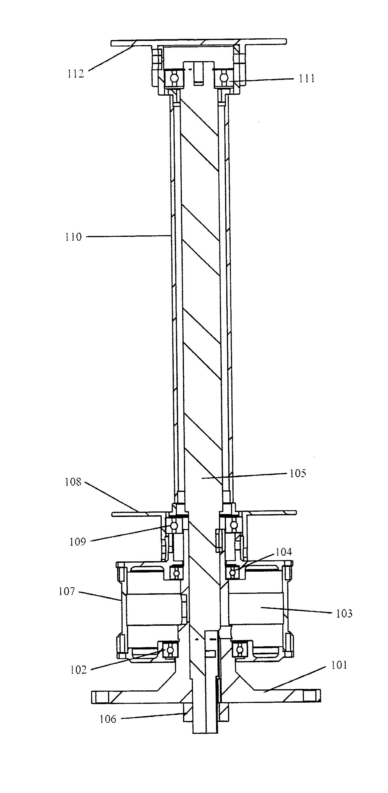
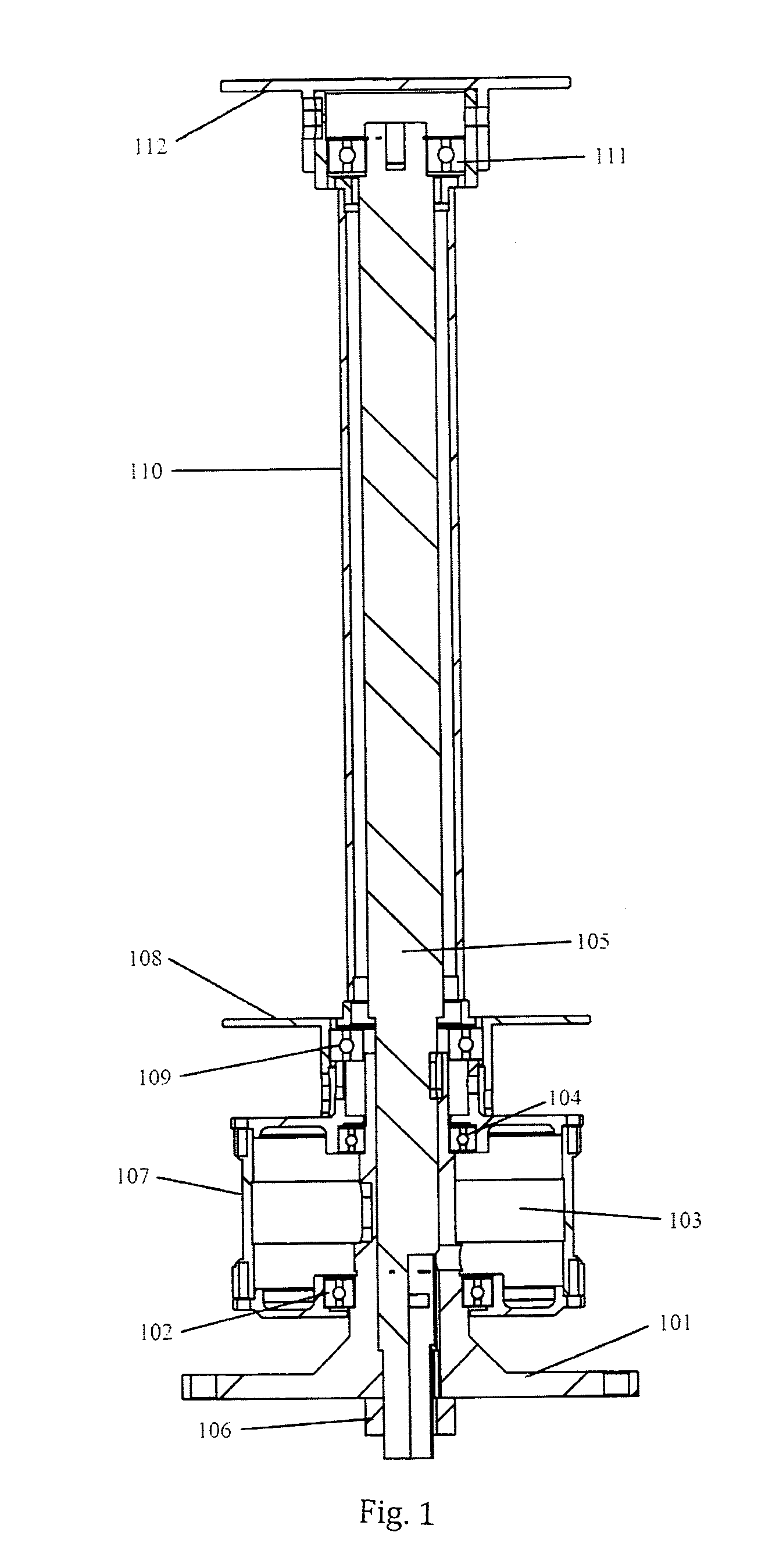
[0019]Adopting the above-mentioned structure, the shaft of the wind turbine may be designed as two shafts, i.e. the wind rotor shaft and the generator shaft. The wind rotor shaft may be a hollow shaft, which may be inserted into the bottom of the generator shaft and be locked. The wind rotor shaft may extend the length of the wind turbine. Pressure is applied to the inner axis from the top to the bottom, with a substantially equal distribution through two or more bearings. The upper, lower and / or midsection connecting arms of the wind rotor may be connected via the flange of the wind rotor shaft through the bearing respectively, and be united together by the drive shaft barrel of the wind rotor. Meanwhile, the wind rotor may be connected with the external rotor of the external rotor generator. Thus, the weight and sideways wind force can be transferred to the tower via the wind rotor shaft bearing(s) and wind rotor shaft therefore preventing the bearing(s) of the generator being stressed due to the wind rotor applying pressure on the generator directly, so as to decrease the start up wind speed of the wind rotor.
[0020]Further advantages of the above-mentioned structure are the maintenance of a low rpm, increased torque, reduced vibrations and reduced noise, thus improved safety of the wind turbine.

Problems solved by technology

The required power of the wind turbine cannot be achieved without enlarging the dimension of the wind rotor.
It is well known that the longer the wind rotor shaft of a vertical axis wind turbine, the more difficult the delivery, erection, windings installation and assembly of the generator.

Method used


Image

  • External Rotor Generator of Vertical Axis Wind Turbine
  • External Rotor Generator of Vertical Axis Wind Turbine
  • External Rotor Generator of Vertical Axis Wind Turbine

Examples


Embodiment Construction

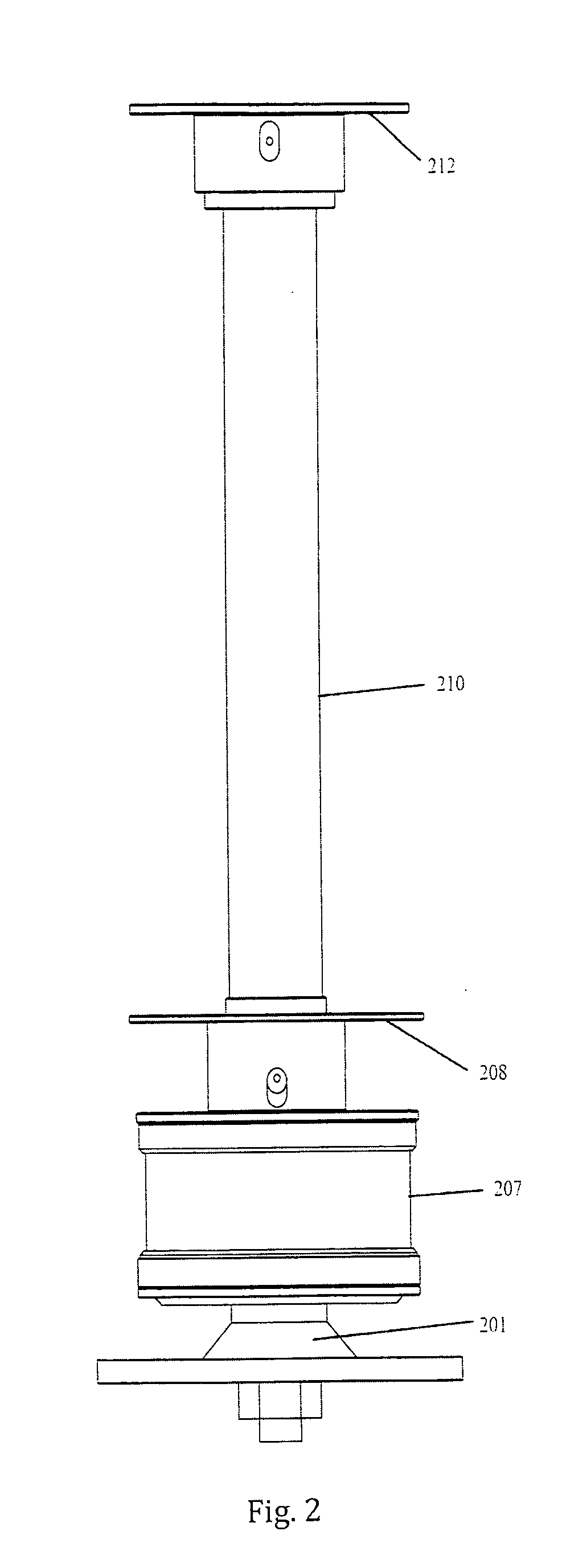
[0026]According to FIG. 1, FIG. 2, FIG. 3 and FIG. 4, the generator shaft 101, 201, 301, 401 is a hollow shaft (refer to FIG. 4) and the stator 103 is sheathed on and kept in locational fit with the generator shaft 101, 201, 301, 401. The wind rotor shaft 105, 405 is inserted into the generator shaft 101, 201, 301, 401 and kept in locational fit with the generator shaft 101, 201, 301, 401, and is locked by locknut 106 of the wind rotor shaft 105, 405 at the bottom.

[0027]The external rotor 107, 207307 of the generator is connected with the generator shaft 101, 201, 301, 401 through the generator upper bearing 104 and lower bearing 102. The wind rotor shaft is arranged on the upper flange 112 and lower flange 108 of the wind rotor. Being sheathed on the wind rotor shaft 105405 the upper bearing 111 and lower bearing 109 of the wind rotor are arranged on the internal of the upper flange 112 and lower flange 108 of the wind rotor, wherein, the lower flange 108 of the wind rotor is conne...


PUM


Abstract

A vertical axis wind turbine characterized in an external rotor generator comprising an external rotor generator and wind turbine arranged on the external rotor generator.

Description

TECHNICAL FIELD[0001]The present invention relates to an external rotor generator for a vertical axis wind turbine.BACKGROUND ART[0002]At present, a wind rotor is usually arranged on an external rotor i.e. a generator enclosure for an external rotor generator of a vertical axis wind turbine. This may increase the friction resistance of the generator rotor by applying the weight of the wind rotor on the main generator shaft, so as to increase the start up speed of the wind rotor. The required power of the wind turbine cannot be achieved without enlarging the dimension of the wind rotor. It is well known that the longer the wind rotor shaft of a vertical axis wind turbine, the more difficult the delivery, erection, windings installation and assembly of the generator.[0003]DE19516504 discloses a wind-driven generator comprising a vertical turbine rotor system positioned perpendicular to the wind direction, with an external rotor and an internal rotor which rotate in opposite directions...

Claims


Application Information

Patent Timeline
Patent Type & Authority Applications(United States)
IPC IPC(8): F03D9/00F03D3/06
CPCF03D3/062F03D9/002Y02E10/74F05B2220/7066H02K7/183F03D11/0008F03D9/25F03D80/70Y02E10/728Y02P70/50F03D13/20
Inventor SONG, HANJUNLIU, YUNBLITTERSWYK, NICOLAS
Owner URBAN GREEN ENERGY
Learn More