
Solvent resistant printhead

a printhead and solvent technology, applied in the field of microfluid ejection devices, can solve the problems of aqueous based inks wet on the surface, aqueous based inks used on other substrates, adhesion problems, etc., to improve the adhesion of the barrier, improve the solvent compatibility of the printhead assembly, and improve the effect of solvent resistan

Inactive Publication Date: 2012-04-19
FUNAI ELECTRIC CO LTD
View PDF1 Cites 2 Cited by
  • Summary
  • Abstract
  • Description
  • Claims
  • Application Information

AI Technical Summary

Benefits of technology

[0010]The above-mentioned and other problems become solved with a solvent-resistant printhead. The printhead having a polymeric material may include a barrier to protect the printhead against corrosion and loss of adhesion that may be caused by exposure to solvent-based inks.
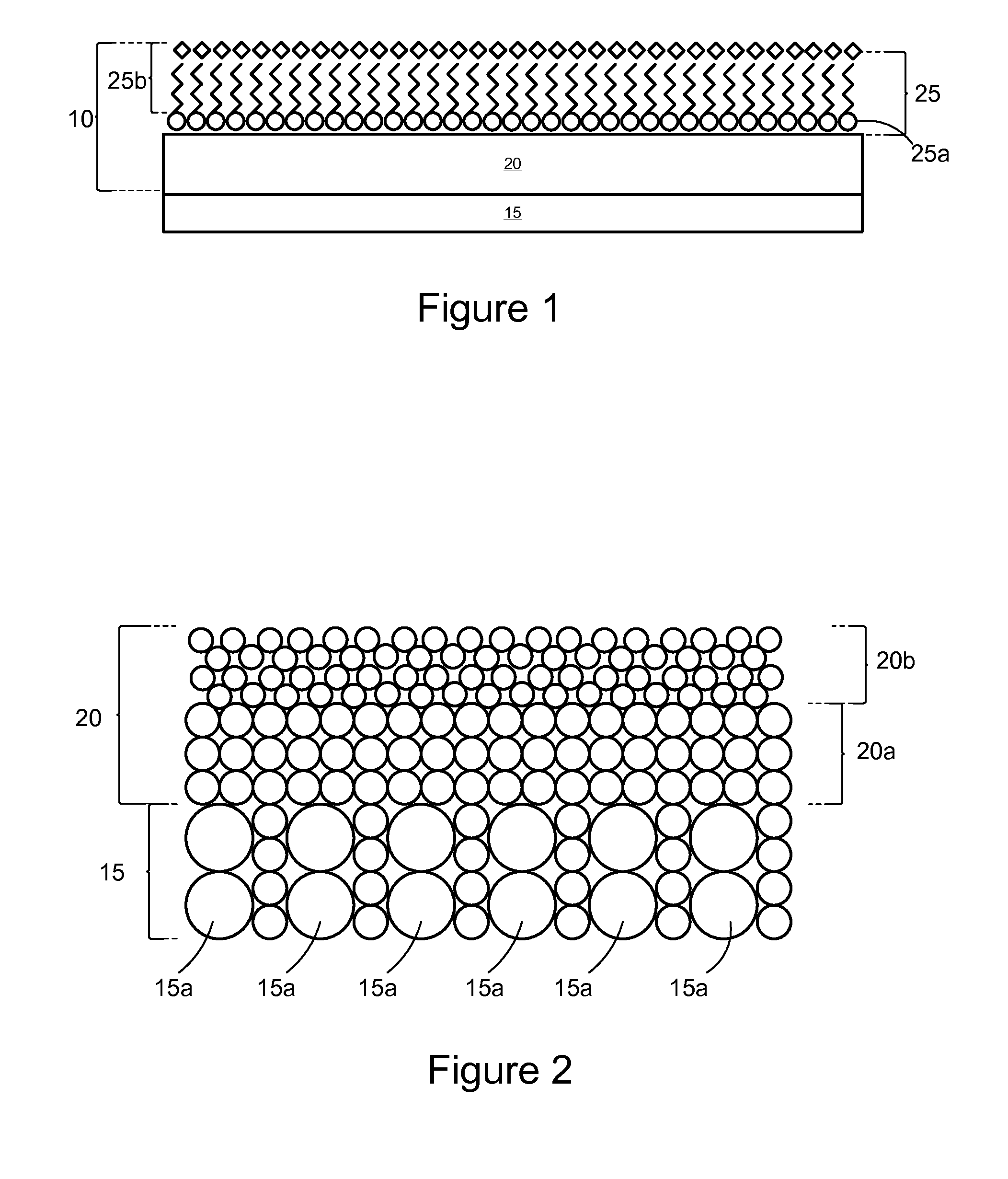
[0012]The barrier may encapsulate all the polymeric based materials and free surfaces on the printhead, leading to improve solvent resistance. Once the barrier is deposited on the printhead assembly, solvent and moisture may be prevented from reaching or penetrating the polymeric materials thus providing corrosion protection and improved solvent compatibility to the printhead assembly. The intercalation of the intercalate layer into the various polymeric materials of the printhead may enable better adhesion of the barrier to the printhead assembly.

Problems solved by technology

Unfortunately, use of the aqueous based inks on other substrates, specifically low surface energy, non-porous media such as PVC, PET, ceramics, PP, coated papers, and other non-porous media used in the industrial market, has shown adhesion issues due to the inability of the aqueous based inks to wet the surface and penetrate into the substrate.
Solvent-based inks, however, may not be compatible with the ablated or nozzle plate materials, encap, diebond, TAB circuits, covercoat and other organic materials used in printheads designed for aqueous based inks.
Diffusion of the solvent and moisture into the material may lead to an accelerated corrosion failure, premature loss of adhesion, and print quality defects.

Method used


Image

  • Solvent resistant printhead
  • Solvent resistant printhead
  • Solvent resistant printhead

Examples


Embodiment Construction

[0017]It is to be understood that the invention is not limited in its application to the details of construction and the arrangement of components set forth in the following description or illustrated in the drawings. The invention is capable of other embodiments and of being practiced or of being carried out in various ways. Also, it is to be understood that the phraseology and terminology used herein is for the purpose of description and should not be regarded as limiting. The use herein of “including,”“comprising,” or “having” and variations thereof is meant to encompass the items listed thereafter and equivalents thereof as well as additional items. Unless limited otherwise, the terms “connected,”“coupled,” and “mounted,” and variations thereof herein are used broadly and encompass direct and indirect connections, couplings, and mountings. In addition, the terms “connected” and “coupled” and variations thereof are not restricted to physical or mechanical connections or couplings...


PUM

PropertyMeasurementUnit
Thicknessaaaaaaaaaa
Thicknessaaaaaaaaaa
Thicknessaaaaaaaaaa

Abstract

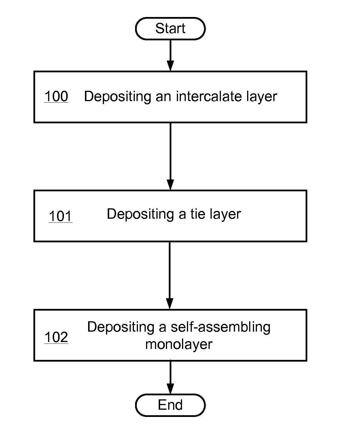
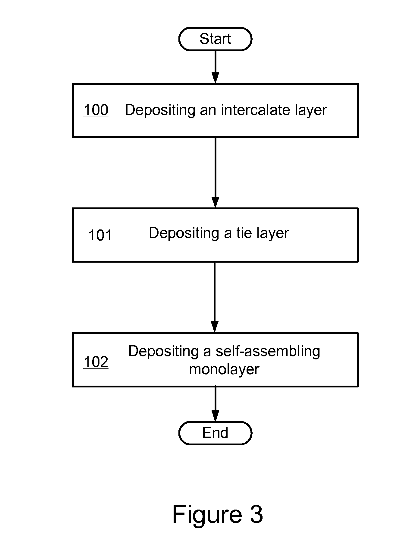
A solvent resistant printhead having a barrier deposited and intercalating into the various polymeric materials on the printhead is disclosed. The deposition process may be performed at the various level of production depending on what material or surface requires protection from the solvent. The barrier may include a base coating and an outer coating. The base coating may include an intercalate layer deposited on the printhead and intercalating into the various polymeric materials and a tie layer deposited on the intercalate layer. The outer coating may be a self-assembled monolayer deposited on the base coating.

Description

CROSS REFERENCES TO RELATED APPLICATIONS[0001]This patent application is related to and claims priority to U.S. Provisional Patent Application Ser. No. 61 / 394,474 entitled “Solvent Resistant Printhead” which was filed on Oct. 19, 2010.STATEMENT REGARDING FEDERALLY SPONSORED RESEARCH OR DEVELOPMENT[0002]None.REFERENCE TO SEQUENTIAL LISTING, ETC.[0003]None.BACKGROUND[0004]1. Technical Field[0005]The present disclosure relates to micro-fluid ejection devices. More particularly, it relates to inkjet printheads using solvent based inks.[0006]2. Description of the Related Art[0007]The art of printing images with micro-fluid technology is relatively well-known. In the field of micro-fluid ejection devices, current nozzle plate materials and the upilex / phenolic ablated materials have been engineered to be compatible with aqueous based inks. The aqueous based inks are suitable for thermal inkjet due to water nucleation kinetics and pumping effectiveness. Aqueous based inks are traditionally ...

Claims


Application Information

Patent Timeline
IPC IPC(8): B41J2/015C23C16/44B32B3/00B32B9/04B32B19/00
CPCB41J2/1606C23C16/0272Y10T428/265C23C16/45555C23C16/401Y10T428/31504Y10T428/31663
Inventor GRAHAM, DAVIDWEAVER, SEAN
Owner FUNAI ELECTRIC CO LTD
Learn More