
Organic Light Emitting Diode Display

a light-emitting diode and organic technology, applied in the field of organic light-emitting diodes (oled) displays, can solve the problems of weak suppression of moisture and oxygen penetration, shorten the useful life of oled displays, and reduce the useful life so as to prevent display failure, increase useful life, and suppress the effect of organic light-emitting elements

Active Publication Date: 2012-04-19
SAMSUNG MOBILE DISPLAY CO LTD
View PDF17 Cites 81 Cited by
  • Summary
  • Abstract
  • Description
  • Claims
  • Application Information

AI Technical Summary

Benefits of technology

[0009]The present invention has been developed in an effort to provide an OLED display having the advantages of preventing a display failure and increasing the useful lifespan by suppressing penetration of external moisture and oxygen into an organic light emitting element by compensating for a weak point of a thin film encapsulation layer.
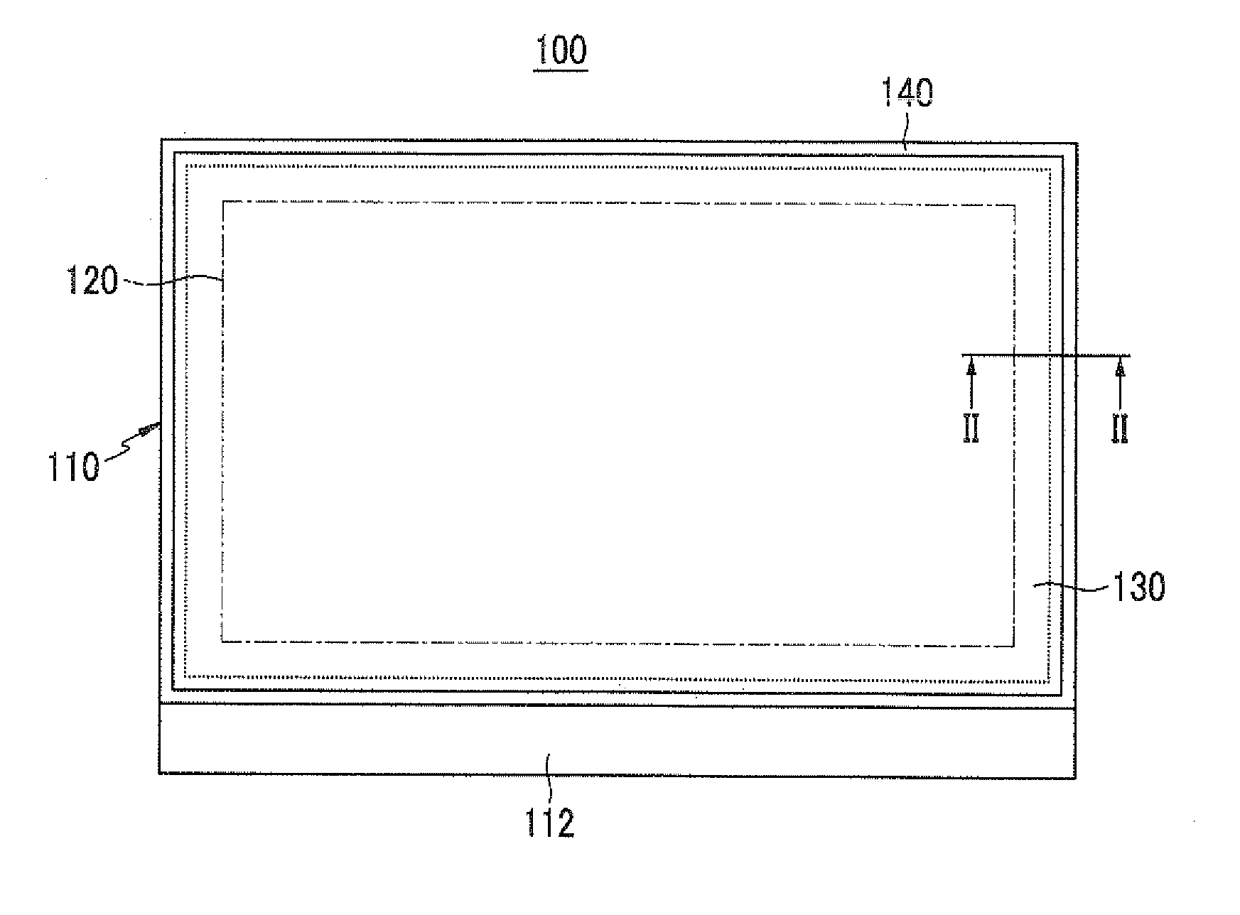
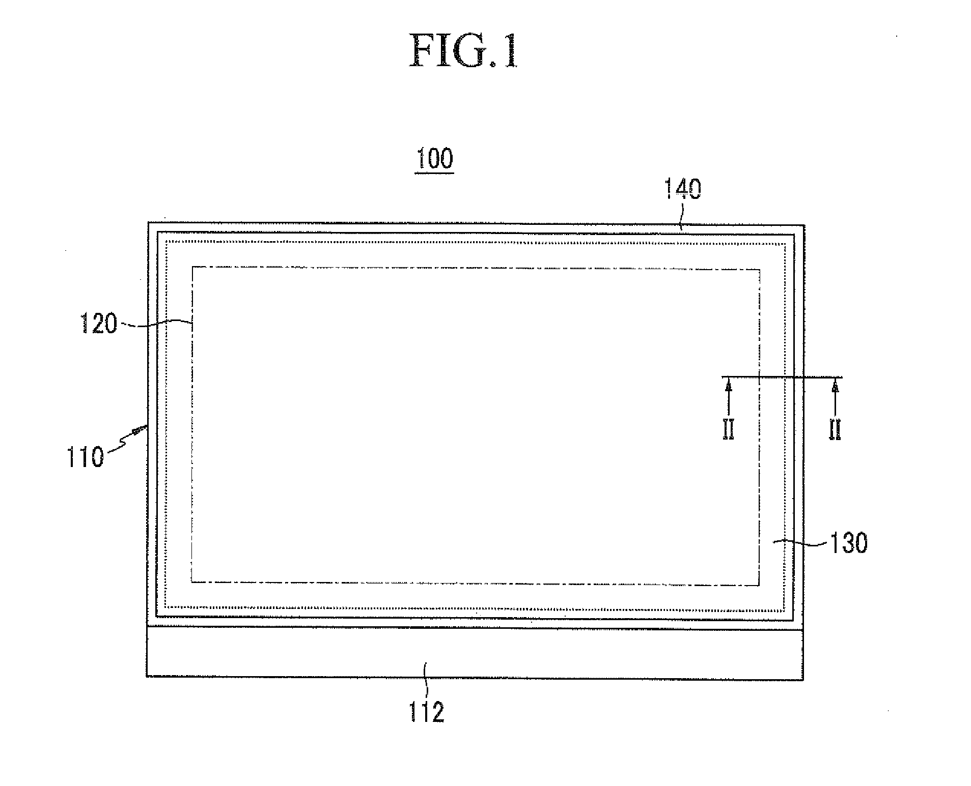
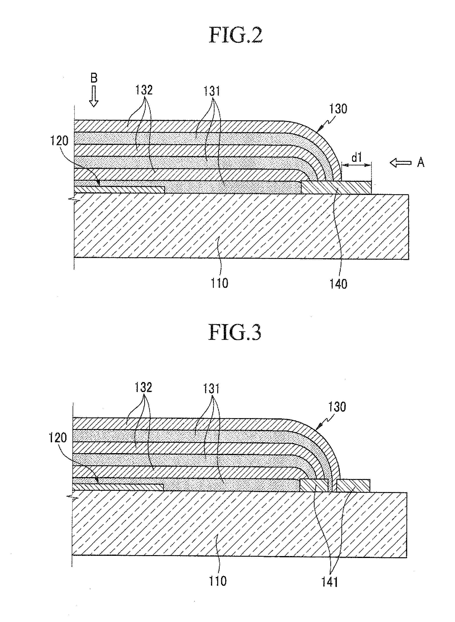
[0019]In an OLED display of the present exemplary embodiment, an interception layer primarily intercepts penetration of external moisture and oxygen in a surface direction of a substrate, and whereas an interface edge of an inorganic film and an organic film is not exposed to the outside, a thin film encapsulation layer secondarily intercepts penetration of external moisture and oxygen. Therefore, the OLED display of the present exemplary embodiment suppresses deterioration of an organic light emitting element positioned at the edge of a display unit, thereby preventing a display failure and increasing useful lifespan.

Problems solved by technology

Deterioration of the organic light emitting element due to such external factors causes a failure of the organic light emitting element and decreases the useful lifespan of the organic light emitting element, and thus packaging technology which seals the organic light emitting element is very important.
However, the thin film encapsulation layer is effective in suppressing penetration of moisture and oxygen according to a stacked direction, i.e., a thickness direction of an inorganic film and an organic film, but it is weak in suppressing penetration of moisture and oxygen in a surface direction of the thin film encapsulation layer and penetration at the edge thereof.
Therefore, as organic light emitting elements which are positioned at the edge of a display area deteriorate, a display failure may occur, and the useful lifespan of the OLED display is shortened.

Method used


Image

  • Organic Light Emitting Diode Display
  • Organic Light Emitting Diode Display
  • Organic Light Emitting Diode Display

Examples


Embodiment Construction

[0030]The present invention will be described more fully hereinafter with reference to the accompanying drawings, in which exemplary embodiments of the invention are shown. As those skilled in the art will realize, the described embodiments may be modified in various different ways, all without departing from the spirit or scope of the present invention.

[0031]The drawings and description are to be regarded as illustrative in nature and not restrictive. Like reference numerals designate like elements throughout the specification. Furthermore, in the drawings, the size and thickness of each element are randomly represented for better understanding and ease of description, and the present invention is not limited thereto.

[0032]In the drawings, the thickness of layers, films, panels, regions, etc. are exaggerated for clarity. In the entire specification, when it is said that any part, such as a layer, film, region or plate, is positioned on another part, it means that the part is direct...


PUM


Abstract

An organic light emitting diode (OLED) display comprises: a substrate; a display unit formed on the substrate and including an organic light emitting element; an interception layer positioned at the outside of the display unit on the substrate; and a thin film encapsulation layer which is formed with a stacked film of an inorganic film and an organic film, which has an end portion contacting the interception layer, and which covers the entire display unit and at least a part of the interception layer.

Description

CLAIM OF PRIORITY[0001]This application makes reference to, incorporates the same herein, and claims all benefits accruing under 35 U.S.C. §119 from an application earlier filed in the Korean Intellectual Property Office on Oct. 19, 2010 and there duly assigned Serial No. 10-2010-0101931.BACKGROUND OF THE INVENTION[0002]1. Field of the Invention[0003]The present invention relates generally to an organic light emitting diode (OLED) display. More particularly, the present invention relates to an OLED display to which thin film encapsulation (TFE) technology is applied.[0004]2. Description of the Related Art[0005]An OLED display is a self luminescent display device that has a self luminescent organic light emitting element to display an image. The organic light emitting element may be deteriorated by penetration of external moisture and oxygen, as well as ultraviolet (UV) rays. Deterioration of the organic light emitting element due to such external factors causes a failure of the orga...

Claims


Application Information

Patent Timeline
Patent Type & Authority Applications(United States)
IPC IPC(8): H01L51/52
CPCH01L51/5256H01L51/5246H10K59/874H10K59/8722H10K59/8731H10K59/126H10K50/8426H10K50/8445H10K50/846
Inventor KIM, TAE-JIN
Owner SAMSUNG MOBILE DISPLAY CO LTD
Learn More