
Sensor device, comprising an optical sensor, a container and a compartmentalization means

a sensor and optical sensor technology, applied in the field of sensor devices, can solve the problems of hydrophilic optical sensor damage, dose-dependent, radiation damage to optical sensor, etc., and achieve the effect of reducing the internal volume of the tube, minimizing the number of reactive particles forming, and easy penetration

Active Publication Date: 2012-04-19
SARTORIUS STEDIM BIOTECH GMBH
View PDF2 Cites 14 Cited by
  • Summary
  • Abstract
  • Description
  • Claims
  • Application Information

AI Technical Summary

Benefits of technology

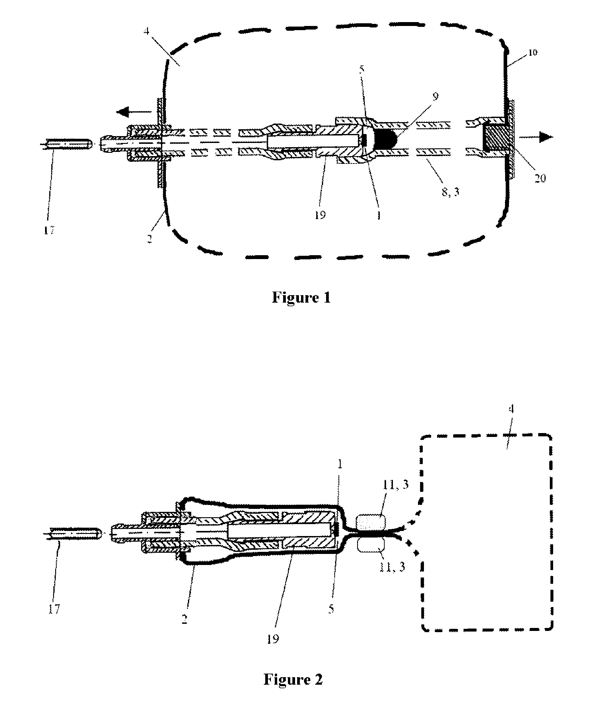
[0011]As per a preferred embodiment of the invention, the optical sensor is sterilizable by radiation whilst maintaining the functionality thereof. The sensitivity towards sterilization, for example by means of ionizing radiation, gamma radiation, UV-C, beta or electron radiation, is reduced by means of the compartmentalization means. By reducing the volume of gas in the direct vicinity of the optical sensor, there is an according reduction in the number of reactive particles formed therefrom, which reactive particles have access to the optical sensor and react with the matrix thereof and with the fluorescent dye or fluorescent dyes. This achieves an improved signal-to-noise ratio and a generally higher sensitivity of the optical sensor with respect to the measurement variable thereof. Here the measurement variables can be e.g. the pH value, the dissolved oxygen concentration or other parameters. The compartmentalization or compartmentalization means can be made undone after the radiation sterilization or before the container is used, e.g. as a bioreactor, without breaking the sterile barrier of the container.
[0022]As per a particularly preferred embodiment of the present invention, the adjacent space is at least partly filled by an aqueous reducing agent. In addition to the protection of the optical sensor from reactive particles as a result of the adjacent space, this also provides protection from direct radiolysis of the sensor chemicals. During radiolysis, for example of the indicator molecules of an optical sensor based on a porous matrix, radical cations are created by the ionizing radiation and these can cause further damage to the sensor chemicals as a result of radical chain reactions. Surprisingly, this damaging effect, which also has a negative influence on the sensor performance, can be largely suppressed by impregnating the sensor matrix with an aqueous reducing agent, such as e.g. 0.1 to thirty-three percent L-ascorbic acid solution. L-ascorbic acid solution, as a radical quencher, effectively suppresses radical chain reactions. Further suitable reducing agents are the salts of L-ascorbic acid, isoascorbic acid, compounds from the class of hydroquinones or glutathione.

Problems solved by technology

Sterilization by means of radiation, more particularly gamma radiation, has proven its worth in the field of disposable products; however, this radiation is damaging to optical sensors.
A disadvantage is the fact that such pH sensor patches, which are based on a hydrophilic carrier matrix, such as e.g. impregnated paper or sol-gel matrices, are damaged, dose-dependent, during radiation sterilization.
Here too a disadvantage lies in the fact that such hydrophilic optical sensors are damaged, dose-dependent, during sterilization using gamma radiation.
There is particularly severe damage to such a sensor patch if it is in contact with a relatively large volume of air or else with conventional protective gasses such as e.g. nitrogen or argon during the radiation sterilization.
Sensors based on porous, hydrophilic matrices are particularly susceptible to this because the sensor chemicals must be present immobilized on the surface or inner surface of the matrix due to operating principles so that the sample to be measured can come into contact with the sensor chemicals.
However, a disadvantage of this is the fact that such a coating is complicated from a technical and mechanical point of view and is connected with high costs; this is something that should be avoided, particularly in the field of disposable products.

Method used


Image

  • Sensor device, comprising an optical sensor, a container and a compartmentalization means
  • Sensor device, comprising an optical sensor, a container and a compartmentalization means
  • Sensor device, comprising an optical sensor, a container and a compartmentalization means

Examples


example

[0043]A plastic container (Cultibag RM, Sartorius Stedim Biotech GmbH, Göttingen / volume: 10 l) is equipped with four pH sensors (HP8, Presens GmbH, Regensburg) on polycarbonate caps. Two of the polycarbonate caps with the sensor chemicals are covered by a simple protective cap that can be sealed in an airtight fashion; in two further sensor caps, the protective cap is additionally filled with twenty percent L-ascorbic acid solution. The sensors are attached to the wall of the container, with the sensor chemicals facing the center of the container. The device is subsequently filled with 10 l air and tightly sealed. Thereupon there is gamma irradiation at 56.0 kGy (Co60 source, Beta-Gamma-Service GmbH & Co. K G, Wiehl). After the irradiation, the sensors are taken from the containers and measured with a transmitter (pH-1 mini, Presens GmbH, Regensburg) in buffers with pH values between 5.7 and 8.5. The sensitivity and hence the quality of the sensors corresponds to the difference in t...


PUM


Abstract

A sensor device has an optical sensor (1), a container (2) and a compartmentalizer (3) that temporarily divides the container into a main space (4) and an adjacent space (5), in which the optical sensor (1) is located. The gas volume in the direct vicinity of the optical sensor (1) is reduced, as are also, consequently, the reactive products generated by radiation sterilization. The adjacent space (5) can be united with the main space (4) after the sterilization as a result of the temporary compartmentalization. The optical sensor is suitable for implementation in containers and laboratory products, such as, for example, disposable bioreactors, that are sterilized by gamma radiation.

Description

BACKGROUND OF THE INVENTION[0001]1. Field of the Invention[0002]The invention relates to a sensor device, having at least one optical sensor, a container and a compartmentalization means.[0003]2. Description of the Related Art[0004]In medical technology and biotechnology, optical sensors are used, in particular, in disposable reactors, mixing reactors and bioreactors or in disposable containers, mixing containers and biocontainers. In these and similar fields of application it is often necessary to sterilize a container before use. Sterilization by means of radiation, more particularly gamma radiation, has proven its worth in the field of disposable products; however, this radiation is damaging to optical sensors. This particularly affects optical sensors based on porous matrices, such as, for example, fluorescence-based pH sensors. Thus an effective protection system, which can simultaneously be implemented in a cost-effective fashion, is required for such sensors.[0005]WO 02 / 05602...

Claims


Application Information

Patent Timeline
IPC IPC(8): H01J5/02
CPCA61L2/081A61L2/28G01N21/90G01N2021/7786G01N21/80
Inventor BAUMFALK, REINHARDWEISSHAAR, STEFANGRELLER, GERHARDRIECHERS, DANIELLUEDERS, JULIAPOLLOSSEK, PETER
Owner SARTORIUS STEDIM BIOTECH GMBH
Learn More