
Controlled-compression direct-power-cycle engine

a power cycle engine and control technology, applied in the direction of engine controllers, machines/engines, electrical control, etc., to achieve the effect of light weight and high fuel efficiency

Inactive Publication Date: 2012-04-19
HU LUNG TAN
View PDF8 Cites 18 Cited by
  • Summary
  • Abstract
  • Description
  • Claims
  • Application Information

AI Technical Summary

Benefits of technology

[0014]It is the main objective of the present invention to provide a controlled-compression direct-power-cycle engine that can operate with a high fuel efficiency and light weight engine structure.
[0015]It is the second objective of the present invention to provide a controlled-compression direct-power-cycle engine that can control the engine power output by shifting the open-time and the shut-time of the servo-intake-valve to adjust the actual-pressure-ratio of the final-compression-process.
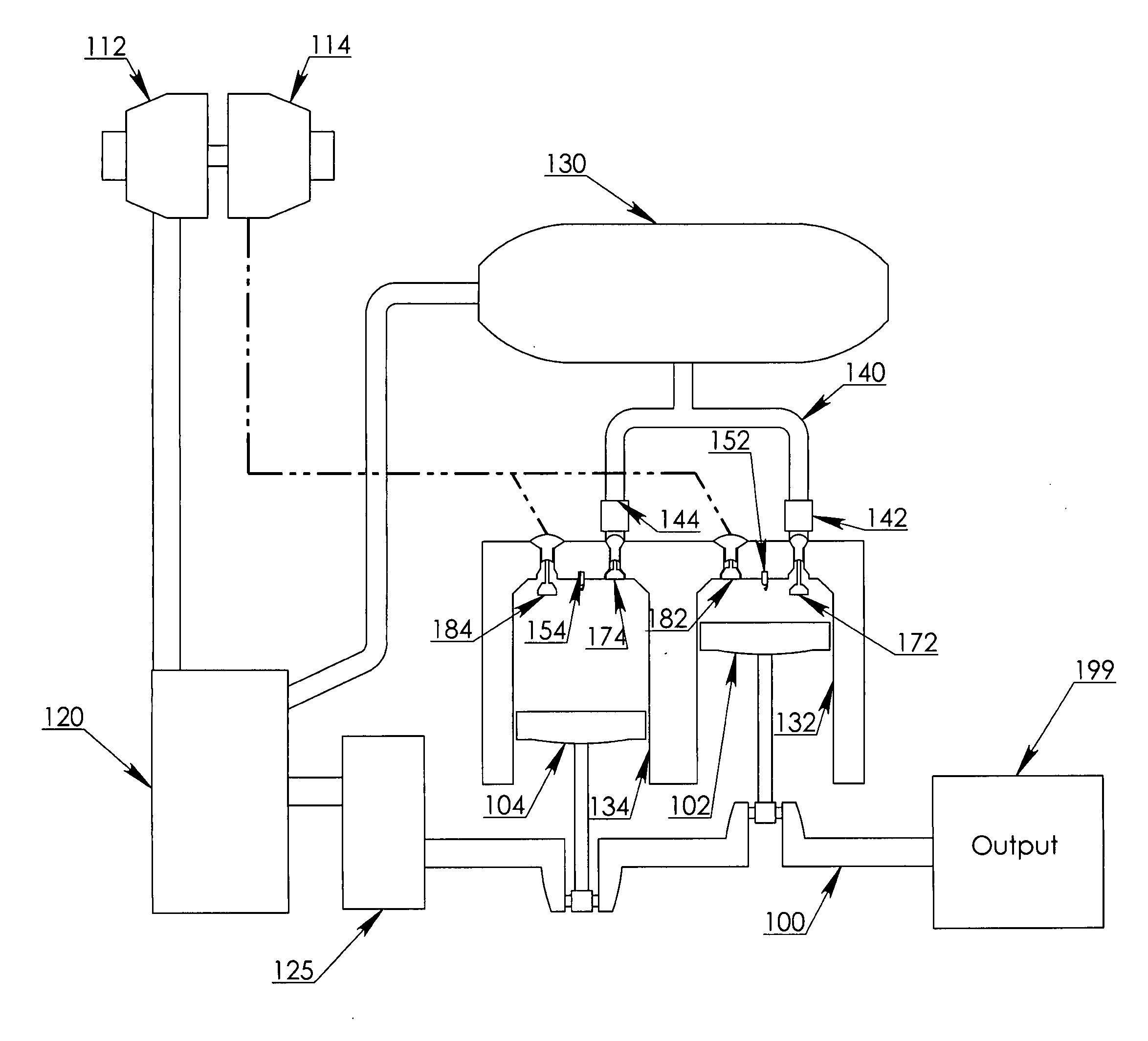
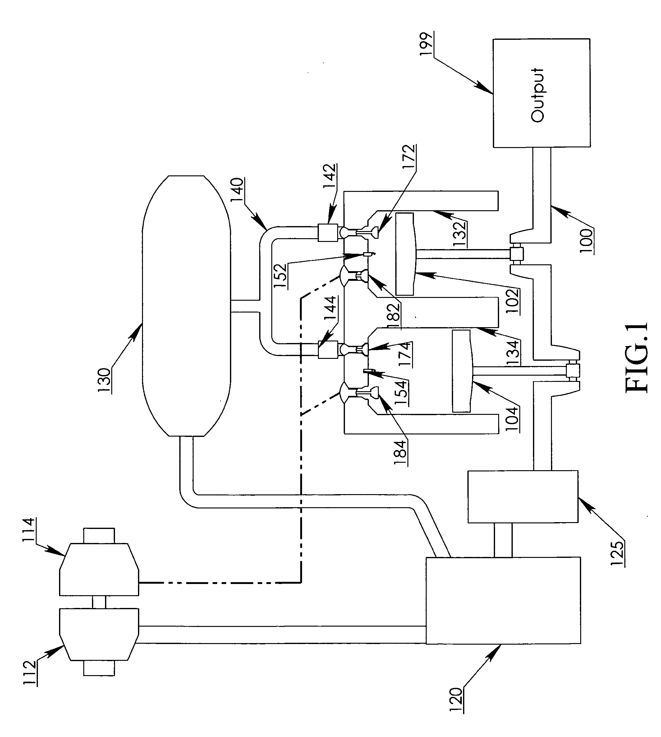
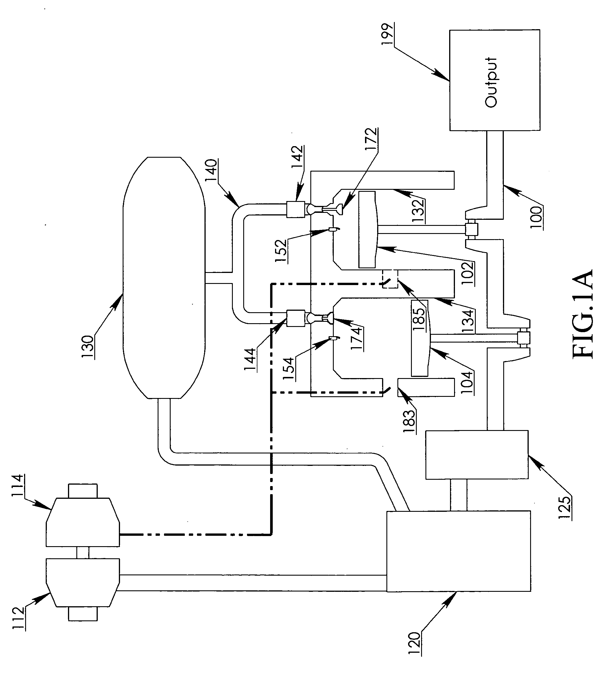
[0016]It is the third objective of the present invention to provide a controlled-compression direct-power-cycle engine that can minimize the energy loss of air-compression by multi-stage compression, wherein the initial-compression-process is performed with a compressor of the turbocharger system, the intermediate-compression-process is performed with an intermediate-compressor, and the final-compression-process is performed with the pistons of the combustion chambers.
[0017]It is the fourth objective of the present invention to provide a controlled-compression direct-power-cycle engine that adjusts the compression capacity of the intermediate-compressor with transmission means to maintain a preset optimum pressure in the cooling-tank, thereby compensating the unstable air-pressure of initial-boost air from the compressor of the turbocharger.
[0018]It is the fifth objective of the present invention to provide a highly efficient air-assistance system for storing the brake power as a compressed air in the cooling-tank with the intermediate-compressor during the braking process.

Problems solved by technology

The initial-compression-process is performed by a turbocharger system because the turbocharger system cannot provide a constant pressure boost to the ambient air, however, the turbocharger system is capable of recovering about 35% of the remained expansion energy in the exhaust gas through the turbine, thereby outputting a flow of low-boost air of about 1.5 bar to 5 bar from the compressor of the turbocharger system during the initial-compression-process.

Method used


Image

  • Controlled-compression direct-power-cycle engine
  • Controlled-compression direct-power-cycle engine
  • Controlled-compression direct-power-cycle engine

Examples


Embodiment Construction

[0026]The pistons in the combustion chambers of the direct-power-cycle will perform a down-stroke and an up-stroke, wherein the TDC of the piston (top dead centre) is referred as 0 degree or 360 degree of the crankshaft reference angle, the BDC of the piston (bottom dead centre) is referred as 180 degree of crankshaft reference angle.

[0027]The direct-power-cycle consists of the initial-compression-process, the intermediate-compression-process, the cooling-process, the servo-intake-process, the final-compression-process, the combustion-process, and the turbine-exhaust-process; wherein the servo-intake-process, the final-compression-process, the combustion-process and the turbine-exhaust-process are performed in the combustion-chambers of the direct-power-cycle engine.

[0028]The ratio of the maximum compression pressure of the combustion chamber to the air-pressure of the cooling-tank is referred as the actual-pressure-ratio of the final-compression-process, wherein this actual-pressur...


PUM


Abstract

The present invention provides a controlled-compression direct-power-cycle engine for performing the direct-power-cycle, wherein the air is compressed with three compression processes and cooled to a controlled temperature before ignition, the engine power output is controlled by both the compressor-transmission and the servo-intake-valve; the three compression processes are the initial-compression-process, the intermediate-compression-process, the final-compression-process, wherein, the initial-compression-process is performed by the turbocharger, the intermediate-compressor-process is performed by a screw type compressor, a rotary type compressor, or a scroll type intermediate-compressor, the final-compression-process is performed by the pistons of the combustion chambers; said intermediate-compressor is coupled to the compressor-transmission for adjusting the compression-capacity according to the instruction signals from the engine control unit, which computes the required compression-capacity by the user's power demand and the pressure in the cooling tank; said final-compression-process adjusts the actual-pressure-ratio with the actuation-time of the servo-intake-valve; said servo-intake-valve is opened for 5-60 degree of crankshaft rotation and is shut at a point between 90 degree BTC and 10 degree BTC according to instruction signals from the engine control unit; wherein the compressor-transmission is set to provide a higher airflow and said servo-intake-valve is shut at an earlier crankshaft reference angle to increase the actual-pressure-ratio of the final-compression-process for operating the direct-power-cycle at a high power output, whereas the compressor-transmission is set to provide a lower airflow and said servo-intake-valve is shut at a later crankshaft reference angle to decrease the actual-pressure-ratio of the final-compression-process for operating the direct-power-cycle at a lower power output.

Description

FIELD OF THE INVENTION[0001]The present invention relates to an internal combustion engine operating on the basis of the direct-power-cycle, and more particularly to an improvement on the reduction of the compression loss and heat loss from internal combustion engine.[0002]The present invention can be used in the field of transportation vehicle and power generation.BACKGROUND OF THE INVENTION[0003]The present invention is an internal combustion engine operating with the direct-power-cycle for improving the fuel efficiency to above 30% and power-to-weight ratio of the engine system.[0004]The fuel efficiency of the present invention is increased by performing a three-stage compression and a control airflow to the combustion chambers by both adjusting the compression-capacity of the intermediate-compressor and shifting the actuation-timing of the servo-intake-valve.[0005]The three-stage compression of the present invention comprises the initial-compression-process, the intermediate-com...

Claims


Application Information

Patent Timeline
Patent Type & Authority Applications(United States)
IPC IPC(8): F02B33/00
CPCF02B25/04F02B25/145F02B29/0437F02B33/22F02B2075/125Y02T10/18F02D23/00F02D41/0007Y02T10/146Y02T10/144F02D13/028Y02T10/12
Inventor HU, LUNG TAN
Owner HU LUNG TAN
Learn More