Control device of a driving apparatus

a technology of control device and driving apparatus, which is applied in the direction of motor/generator/converter stopper, dynamo-electric converter control, shape/form/construction, etc., and can solve problems such as reduced efficiency, increased copper loss, and inability to control

Inactive Publication Date: 2012-04-05
AISIN AW CO LTD
View PDF0 Cites 10 Cited by
  • Summary
  • Abstract
  • Description
  • Claims
  • Application Information

AI Technical Summary

Benefits of technology

[0007]Thus, the present invention provides technology capable of keeping induced voltage within a voltage resistance limit of an inverter, witho

Problems solved by technology

The induced voltage generated in the stator coil becomes higher as the rotation speed of the rotor increases, and if the induced voltage exceeds the driving voltage, control may no longer be possible.
However, when field-weakening control is performed, the current that flows through the stator coil increases with respect to the torque output from the rotary electric machine, so copper loss increases and efficiency decreases.
However, when seeking efficiency, there are cases in which a strong field flux is necessary even when operating at high speed.
Therefore, if induced voltage that greatly exceeds the power supply voltag

Method used


Image

  • Control device of a driving apparatus
  • Control device of a driving apparatus
  • Control device of a driving apparatus

Examples


Embodiment Construction

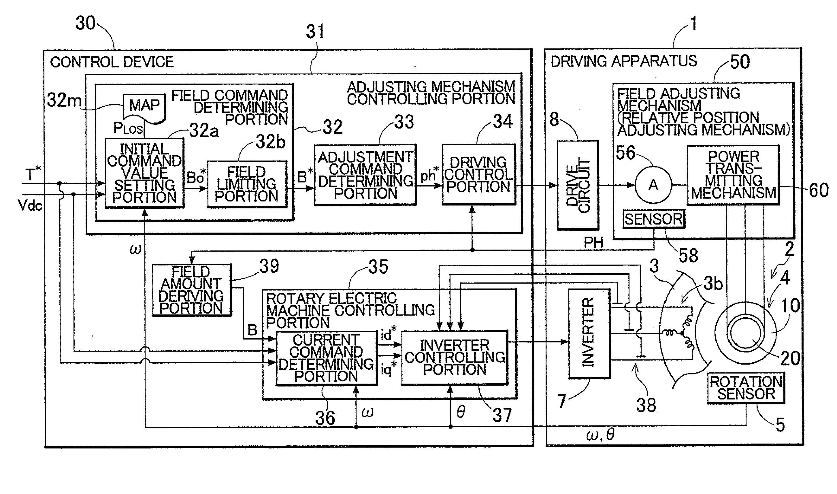
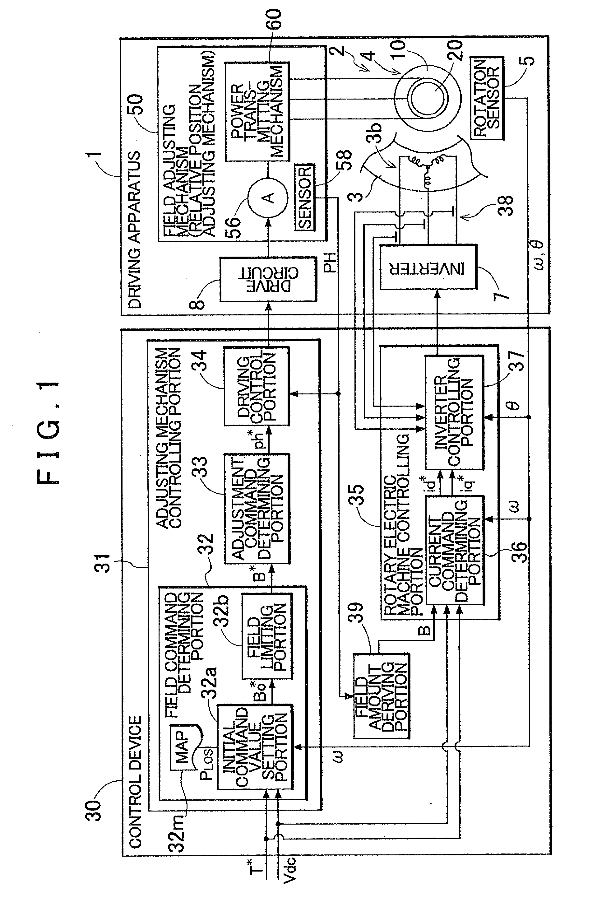
[0025]Hereinafter, a preferred example embodiment of the present invention will be described with reference to the accompanying drawings. FIG. 1 is a view showing a frame format of the overall structure of a driving apparatus 1 and a control device 30 of the driving apparatus, according to the present invention. As shown in FIG. 1, the driving apparatus 1 includes a rotary electric machine 2 and a field adjusting mechanism 50, an inverter 7 that drives the rotary electric machine 2, and a drive circuit 8 that drives the field adjusting mechanism 50. The rotary electric machine 2 includes a rotor 4 that has permanent magnets, and a stator 3 that has a coil (i.e., a stator coil) 3b. The rotor 4 is configured to change a field flux that links to the coil 3b that generates a rotating magnetic field according to the relative positions, in the circumferential direction, of a first rotor 20 that is an inner rotor and a second rotor 10 that is an outer rotor. That is, the rotary electric ma...


PUM


Abstract

A control device for a driving apparatus configured with a rotary electric machine having a rotor with a permanent magnet and a stator having a coil. A field adjusting mechanism is configured to change a field flux supplied by the rotor, and an inverter is connected to the coil. A field command determining portion is configured to determine a field command value that serves as a target for the field flux that is adjusted by the field adjusting mechanism, based on at least a rotation speed of the rotor, with a field limiting value, that is set according to the rotation speed of the rotor within a range in which induced voltage that is induced in the coil will not exceed a voltage resistance of the inverter, as an upper limit.

Description

INCORPORATION BY REFERENCE[0001]The disclosure of Japanese Patent Application No. 2010-222798 filed on Sep. 30, 2010 including the specification, drawings and abstract is incorporated herein by reference in its entirety.BACKGROUND OF THE INVENTION[0002]The present invention relates to a control device of a driving apparatus that includes a variable magnetic flux-type rotary electric machine in which a field flux provided by a rotor having a permanent magnet can be adjusted, and a mechanism that adjusts this field flux.DESCRIPTION OF THE RELATED ART[0003]Interior permanent magnet synchronous motors (IPMSM) that have a rotor with permanent magnets embedded inside of them are widely used. With an IPMSM, the permanent magnets are typically fixed to a rotor core, so the magnetic flux generated by the rotor is constant. The induced voltage generated in the stator coil becomes higher as the rotation speed of the rotor increases, and if the induced voltage exceeds the driving voltage, contr...

Claims


Application Information

Patent Timeline
IPC IPC(8): H02P25/00H02K21/12H02K1/27H02P6/08H02P6/17H02P6/28
CPCH02P25/021H02P23/009H02P25/24H02P25/024
Inventor HISADA, HIDEKIISHIKAWA, MASAMI
Owner AISIN AW CO LTD
Why Eureka
Try Eureka