Electroactive elastomer actuator and method for the production thereof

Inactive Publication Date: 2012-04-05
FRAUNHOFER GESELLSCHAFT ZUR FOERDERUNG DER ANGEWANDTEN FORSCHUNG EV
View PDF10 Cites 7 Cited by
  • Summary
  • Abstract
  • Description
  • Claims
  • Application Information

AI Technical Summary

Benefits of technology

[0008]The invention is an electroactive elastomer actuator having at least one first band-shaped electroactive elastomer coating and at least one first and one second surface electrode, which are separated by the at least one first electroactive elastomer coating, on the one hand, to have the advantages of stability and actuator efficiency connected to stack actuators known per se and, on the other hand, have the technically simple and cost-effective production mode of actuators manufactured in rolled construction. It is also to be possible to use the electroactive elastomer actuator according to the invention as a modular unit for an expanded construction and expansion of larger dimensioned elastomer actuator systems.
[0010]In contrast to the prior art meandering folding technique, which used the known stacked actuators made of film bands, which are coated on both sides with elastically deformable surface electrodes, made of electroactive elastomers, the band-shaped coating material according to the invention allows technically simple winding on a coil form, so that the lower first surface electrode in the coating material makes contact through the winding procedure with the surface of the second electroactive elastomer layer. As a result, no electrical short circuits occur between two surface electrodes integrated in the coating material. On the other hand, the flat configuration of the plurality of stacked coating material layers contact in a one on top of another allows the advantages of a stack actuator to be used, in that the actuator effect can be used in the thickness direction relative to the individual coating material layers.
[0014]However, with a plate-like configuration of the coil form on which winding occurs around the coil form with the band-shaped coating material under pre-tension, it is particularly advantageous for the coil form to have a high stiffness in the wraparound direction, so that the coil form is prevented from being subjected to undesired deformation due to the applied pre-tension during the winding process.
[0016]In particular materials or workpieces formed into plates are suitable for this purpose, which have an anisotropic stretching behavior in which the workpiece is suitably structured or is composed of multiple material components. The use of fiber-reinforced plastics is possible for this purpose with suitable fiber orientation providing a desired anisotropy behavior. For example, unidirectionally oriented fibers which stiffen the matrix material in one spatial direction may be implemented in a yielding matrix material , which ensure stiffness in the wraparound direction. However, the matrix material yields orthogonally to the fiber extension. It is also possible to supplement a plate-shaped coil form comprising a stretchable elastomer with at least one and preferably two rigid rod-shaped bodies which flank the coil form on both sides, to make the coil form rigid in the direction of longitudinal extension, but remains stretchable the direction orthogonal thereto.

Problems solved by technology

However, electroactive polymer stack actuators have the disadvantage of requiring complex production, since the individual coating material layers must be stacked one over another with great precision by corresponding folding.
But actuators configured as hollow rolled bodies, with an actuator action direction oriented in the tube longitudinal axis, have stability problems, caused by the individual polymer band windings being subject to deformations in the event of an axial compression load because their thin-walled overall cylindrical shape impairs the actuator action.
That is, coating thickness variations in the wound polymer band coatings remain unused or unconsidered.

Method used


Image

  • Electroactive elastomer actuator and method for the production thereof
  • Electroactive elastomer actuator and method for the production thereof
  • Electroactive elastomer actuator and method for the production thereof

Examples


Embodiment Construction

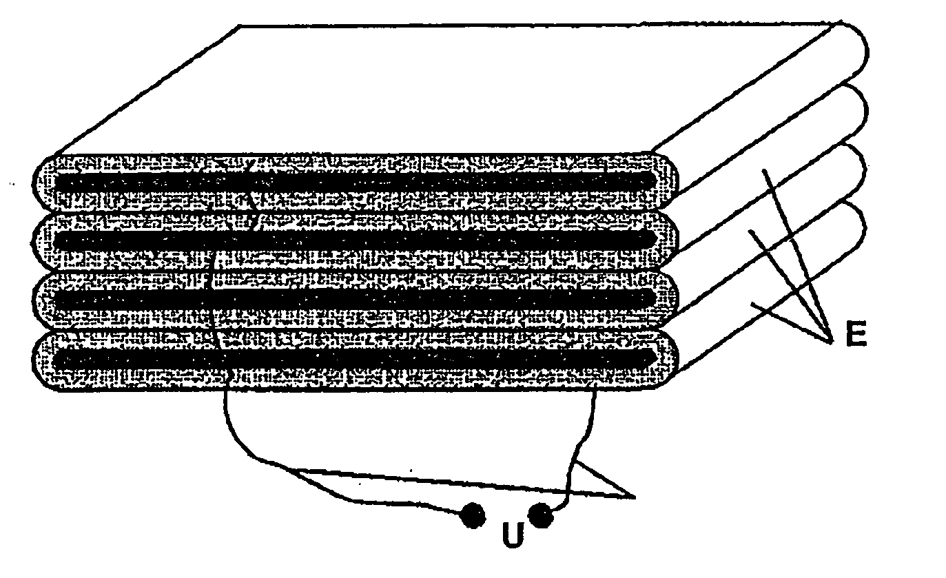
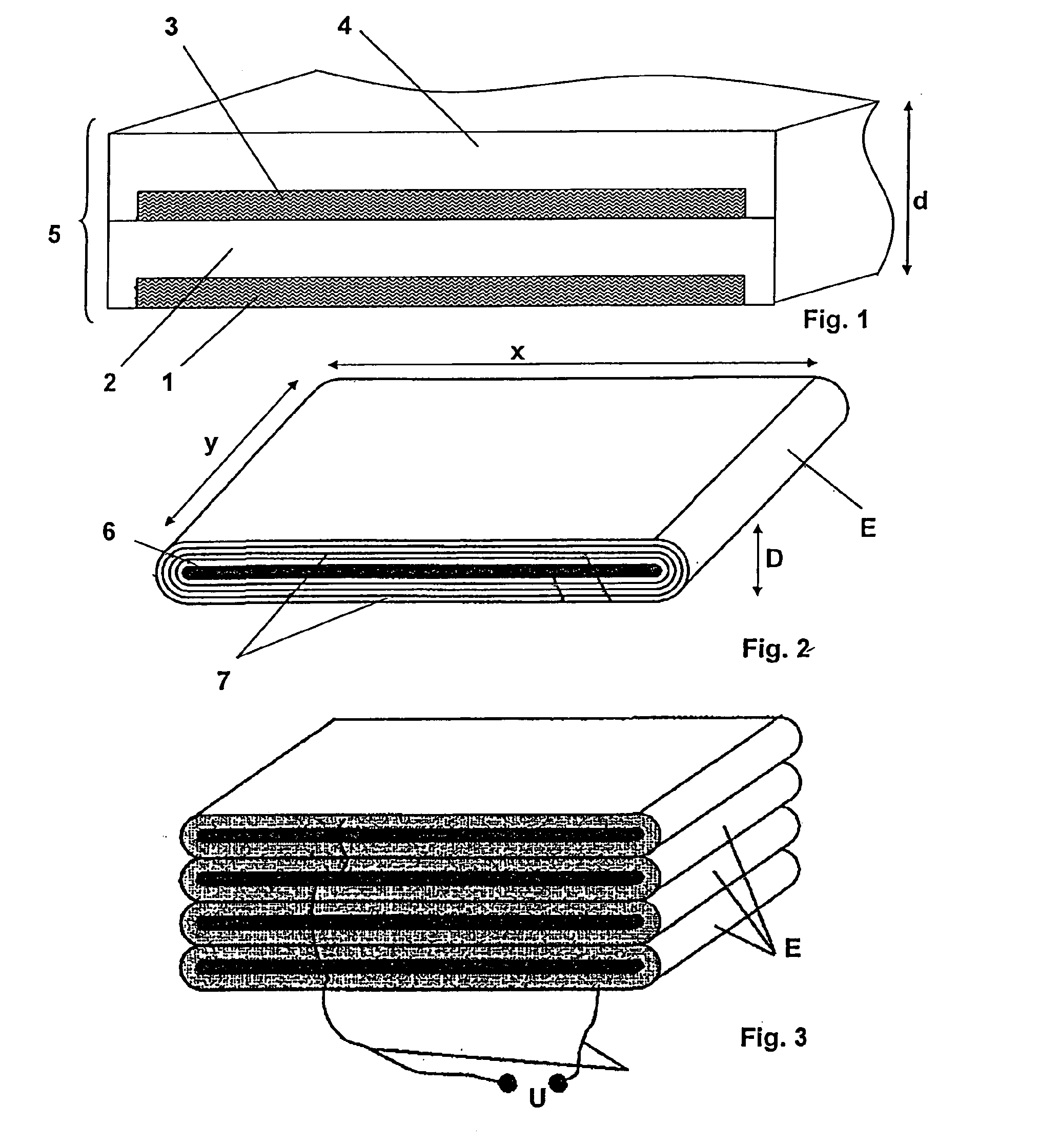
[0026]A double film which is band-shaped is shown in FIG. 1 for the construction and production of an electroactive elastomer actuator according to the invention. The double film has a first surface-elastic surface electrode 1, a first electroactive elastomer coating 2, a second surface-elastic surface electrode 3, and a further second electroactive elastomer coating 4. The band-shaped coating material 5, which is configured as a double film, can be produced in the course of an extrusion process or by gluing together two elastomer coatings, which are each provided on one side with a surface electrode. In the illustrated exemplary embodiment, the first and second elastomer coatings 2 and 4 each laterally enclose the surface electrodes 1 and 3, whereby electrical short circuits, for example, due to temporarily occurring moisture bridges, can be prevented.

[0027]The coating material 5, which is to be stockpiled, is wound around a plate-shaped coil form 6 to produce an electroactive elas...


PUM


Abstract

Described is an electroactive elastomer actuator having at least one first band-shaped electroactive elastomer coating and at least one first and one second surface electrode, which are separated by the at least one first electroactive elastomer coating. At least one second electroactive elastomer coating is applied to a surface of the second surface electrode facing away from the electroactive elastomer coating, which forms a band-shaped coating material jointly with the first and second surface electrodes and the first elastomer coating located between the two surface electrodes. The band-shaped coating material is wound around a flat coil form while forming at least two coating material layers. A surface of the first surface electrode facing away from the first elastomer coating makes surface contact with the second electroactive elastomer coating.

Description

BACKGROUND OF THE INVENTION[0001]1. Field of the Invention[0002]The invention relates to an electroactive elastomer actuator comprising at least one band-shaped electroactive elastomer coating and at least one first and one second surface electrode, which are separated by the at least one first electroactive elastomer coating and furthermore, a method for the production of an electroactive elastomer actuator.[0003]2. Description of the Prior Art[0004]Electroactive elastomer actuators use the converter principle of dielectric elastomers, which belong to the group of electroactive polymers (EAP in short) and are capable of converting electrical energy directly into mechanical work. In contrast to piezoelectric ceramics, which have comparable energy converter properties, electroactive elastomers have very much higher extension properties of greater than 300% and allow substantially free shaping capability at very much lower material density. These properties are used in a way known per...

Claims


Application Information

Patent Timeline
IPC IPC(8): H01L41/083H01L41/04B32B37/14B32B37/02B32B37/12H01L41/45
CPCH01L41/083H01L41/45H01L41/27H10N30/50H10N30/05H10N30/098
Inventor KAAL, WILLIAMHEROLD, SVENMELZ, TOBIAS
Owner FRAUNHOFER GESELLSCHAFT ZUR FOERDERUNG DER ANGEWANDTEN FORSCHUNG EV
Why Eureka
Try Eureka