
Radiator module for commercial motor vehicles

a technology for commercial motor vehicles and radiators, applied in the direction of superstructure subunits, stationary conduit assemblies, lighting and heating apparatus, etc., can solve the problems of increased height of radiator blocks, increased heat sinks, and inability to encroach on the vehicle, and achieve the effect of simple arrangemen

Inactive Publication Date: 2007-01-04
AGCO GMBH
View PDF4 Cites 6 Cited by
  • Summary
  • Abstract
  • Description
  • Claims
  • Application Information

AI Technical Summary

Benefits of technology

[0007] A particularly technically simple arrangement of the invention is provided if the second tank part is an integrated component of the support plate, in particular cast or otherwise formed as one piece with the support plate.

Problems solved by technology

With constant overall height of the coolant tank, which is specified by the radiator manufacturer, this leads to a greater height of the radiator block and therefore an increase in the heat sink.
For example, it may happen that the coolant radiator assumes a position in which sufficient space underneath the support plate is not available for the coolant tank to be accommodated in the support plate over the entire width of the coolant radiator.
With conventionally oriented coolant radiators such encroachment is not possible.

Method used


Image

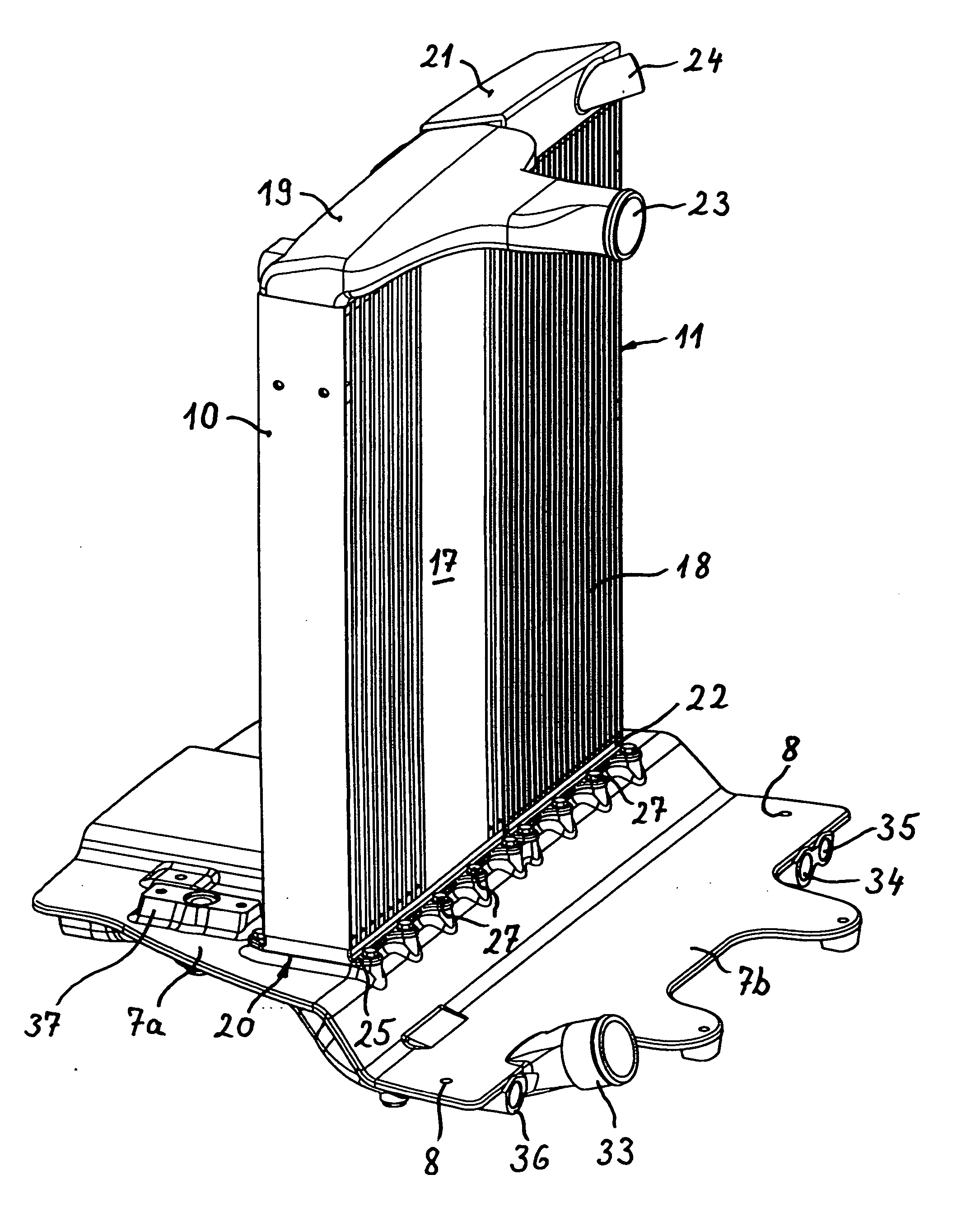
  • Radiator module for commercial motor vehicles
  • Radiator module for commercial motor vehicles
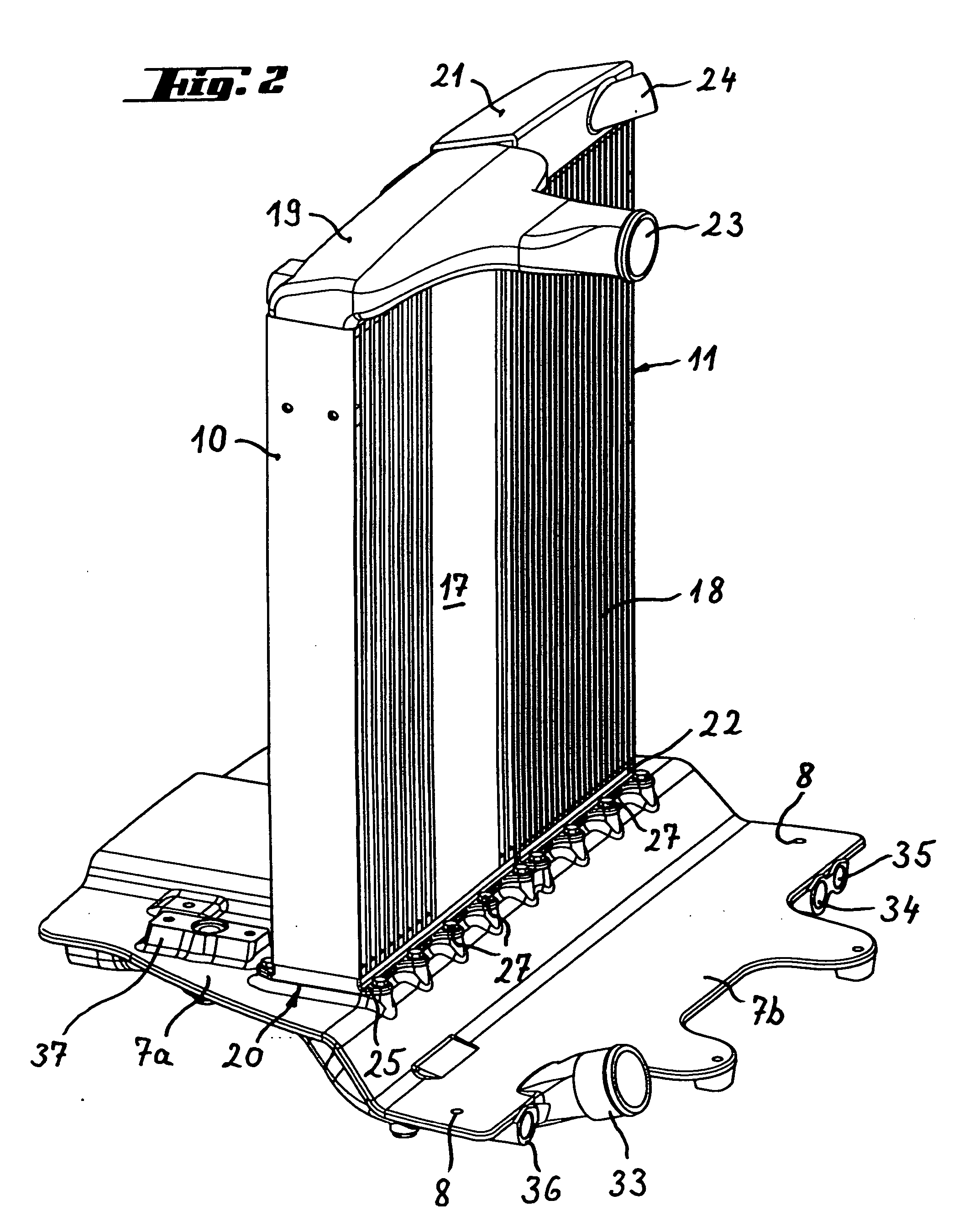
  • Radiator module for commercial motor vehicles

Examples


Embodiment Construction

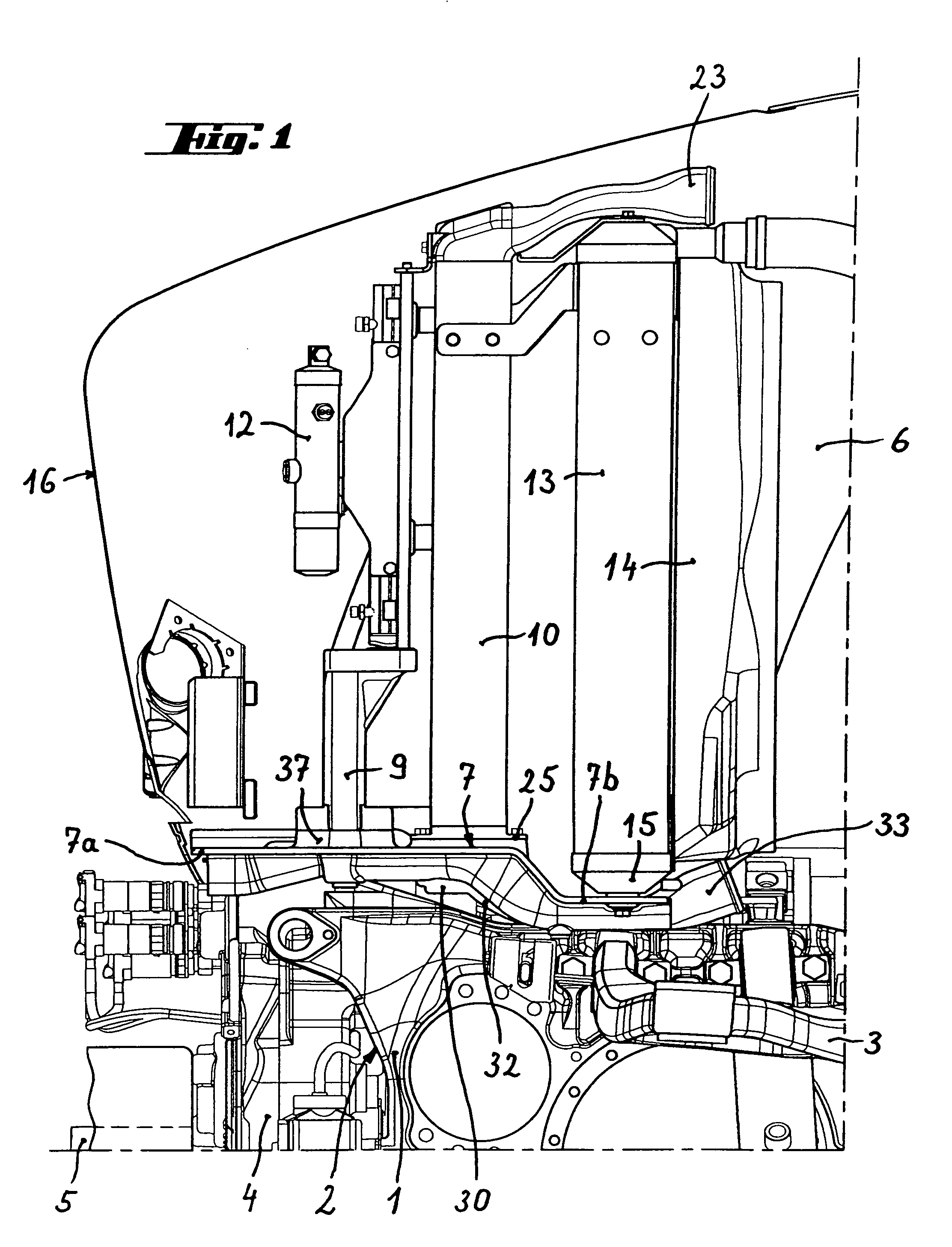
[0016] As is evident from FIG. 1, two laterally spaced side members 1, which are part of a front axle housing 2 extend fore and aft and are oriented substantially parallel to each other to form the chassis at the front end of an agricultural tractor. Only one of these side members 1 is visible in FIG. 1. An upper wishbone of a wheel suspension indicated with the reference numeral 3, which is linked to the side members 1, is also shown. In the front region of the front axle housing 2 a transmission casing 4, in which a variable transmission for driving a front power take-off shaft 5 is accommodated, is arranged between the side members 1. The rear part of the transmission casing 4 has its highest point roughly in the centre between the side members 1, which drops away towards the side members 1.

[0017] Likewise in the front area of the front axle housing 2 a radiator module 6 sits on the side members 1. The radiator module 6 consists of a support plate 7 as well as several coolant ra...


PUM


Abstract

A radiator module for commercial motor vehicles, in particular for agricultural tractors, has a support plate (7) fixed to the chassis and at least one coolant radiator (10) fixed to the support plate. The radiator has a radiator block (17) and two coolant tanks (19, 20) oriented at opposite ends of the block with one tank (20) adjacent the support plate (7) and one (19) spaced away form the support plate. In order to increase the cooling performance of the radiator module (6) despite keeping the installation space above the support plate (7) constant it is proposed that the coolant tank near the plate (20) is constructed from two mutually complementing tank parts (26, 28). The first tank part (26) is assigned to the radiator block (17) and has an encircling flange (25) for pressure sealed attachment of the coolant radiator (10) on the support plate (7). A second tank part (28) is assigned to the support plate (7). By dividing the coolant tank (20) into two parts, one on the radiator block (17) and one on the support plate (7) the effective heat sink area of the coolant radiator (10) can be substantially increased. On the one hand the enlargement is due to the fact that the flange (25) encircling the first tank part also serves to attach the coolant radiator on the support plate and in this region an assembly gap is therefore left between these components. On the other hand the enlargement is due to the fact that by moving part of the coolant tank under the surface of the support plate, the overall height of the coolant radiator is increased accordingly.

Description

BACKGROUND OF THE INVENTION [0001] The invention relates to a radiator module for commercial motor vehicles, in particular for agricultural tractors, which comprises a support plate fixed to the chassis and at least one coolant radiator fixed to the support plate, the radiator consisting of a radiator block and two coolant tanks oriented one at each end of the block, the radiator being supported on the plate by one of the coolant tanks. [0002] A radiator module of this kind is known for agricultural tractors (our product), in which the support plate is implemented as a welded part and is mounted in the front axle region of the tractor directly in front of the engine in an approximately horizontal plane on laterally spaced side members, which form the chassis. A transmission casing, via which a front power take-off shaft can be driven at a variable speed of revolution is accommodated between the side members. For space reasons the transmission casing extends relatively far upwards, s...

Claims


Application Information

Patent Timeline
Patent Type & Authority Applications(United States)
IPC IPC(8): B60K11/04B62D25/08F28D1/04F28F9/00
CPCB60K11/04B60Y2200/221B62D25/084F28D1/0435F28F9/002F28D2021/0084F28D2021/0089F28D2021/0094F28D2021/0082F28D1/04F28F9/00F28F9/02
Inventor HONZEK, ROBERTMARINER, GERHARDNAEGELE, GUIDORATHKE, GERDSCHWARZ, GEORGTSCHULLIK, JUERGEN
Owner AGCO GMBH
Learn More