
Process scheduling system, method, and program

a process scheduling and process technology, applied in the field of system, method, and program, can solve the problems of deteriorating the surface state of the roller, limited thickness difference, and flaw on a wide slab rolled later, and achieve the effect of high speed

Inactive Publication Date: 2012-03-29
IBM CORP
View PDF7 Cites 9 Cited by
  • Summary
  • Abstract
  • Description
  • Claims
  • Application Information

AI Technical Summary

Benefits of technology

[0038]According to the present invention, by forming a grid graph from each of a direct slab sequence and an inventory slab sequence and weighting edges in the graph based on attributes of each individual slab, a combined sequence of direct slabs and inventory slabs can be calculated as a shortest path search problem. This has an advantage of finding an optimal combined sequence solution at high speed.

Problems solved by technology

When a plurality of slabs are rolled one after another by the rollers, the surface state of the rollers deteriorates gradually.
This being so, a groove left on a roller surface by a narrow slab rolled earlier may cause a flaw on a wide slab rolled later.
Furthermore, in the case of successively rolling two slabs that differ in thickness, the difference in thickness is limited to a predetermined range according to specifications of rolling equipment and the like.
Besides, to prevent a decrease in roller durability, thin slabs in particular cannot be successively rolled in large numbers.

Method used


Image

  • Process scheduling system, method, and program
  • Process scheduling system, method, and program
  • Process scheduling system, method, and program

Examples


Embodiment Construction

[0046]An embodiment of the present invention is described below with reference to drawings. The same objects are designated by the same reference numbers in the drawings, unless otherwise indicated. It is to be understood that the following describes merely an embodiment of the present invention, which is not intended to limit the scope of the present invention.

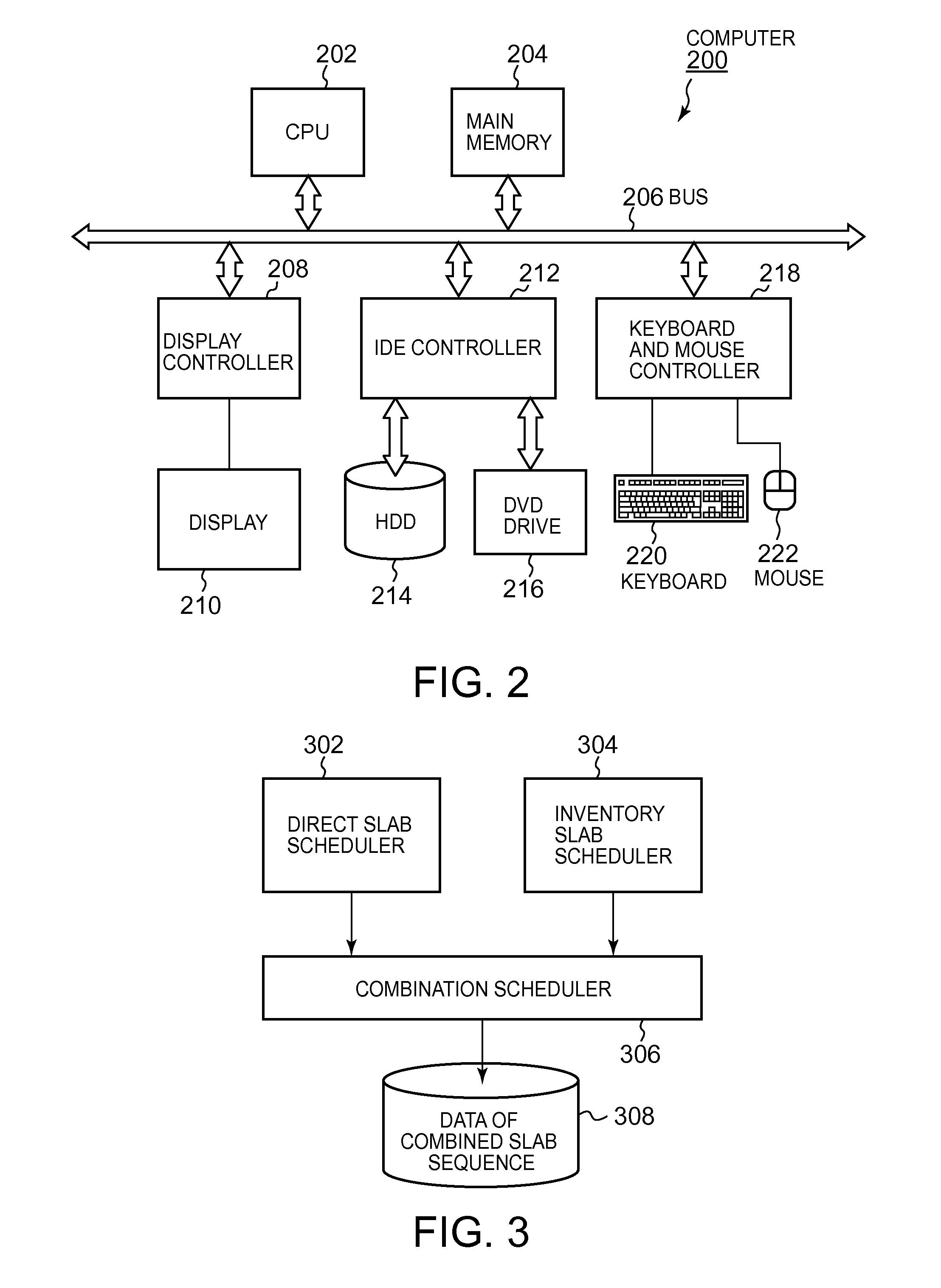
[0047]FIG. 2 is a block diagram of a hardware structure for implementing the method according to the present invention. In FIG. 2, a computer 200 includes a CPU 202 and a main memory 204 that are connected to a bus 206. The main memory 204 has a storage capacity of 1 GB or more, and preferably 4 GB or more. A larger capacity of the main memory 204 is more preferable for loading all vertex data of a graph described later and the like. The CPU 202 is preferably based on an architecture of 32 bits or 64 bits. For example, Pentium® 4,Core™ 2 DUO, Xeon® by Intel Corporation, Athlon® by AMD, and the like can be used for the CPU 202...


PUM

PropertyMeasurementUnit
timeaaaaaaaaaa
weightaaaaaaaaaa
thicknessesaaaaaaaaaa

Abstract

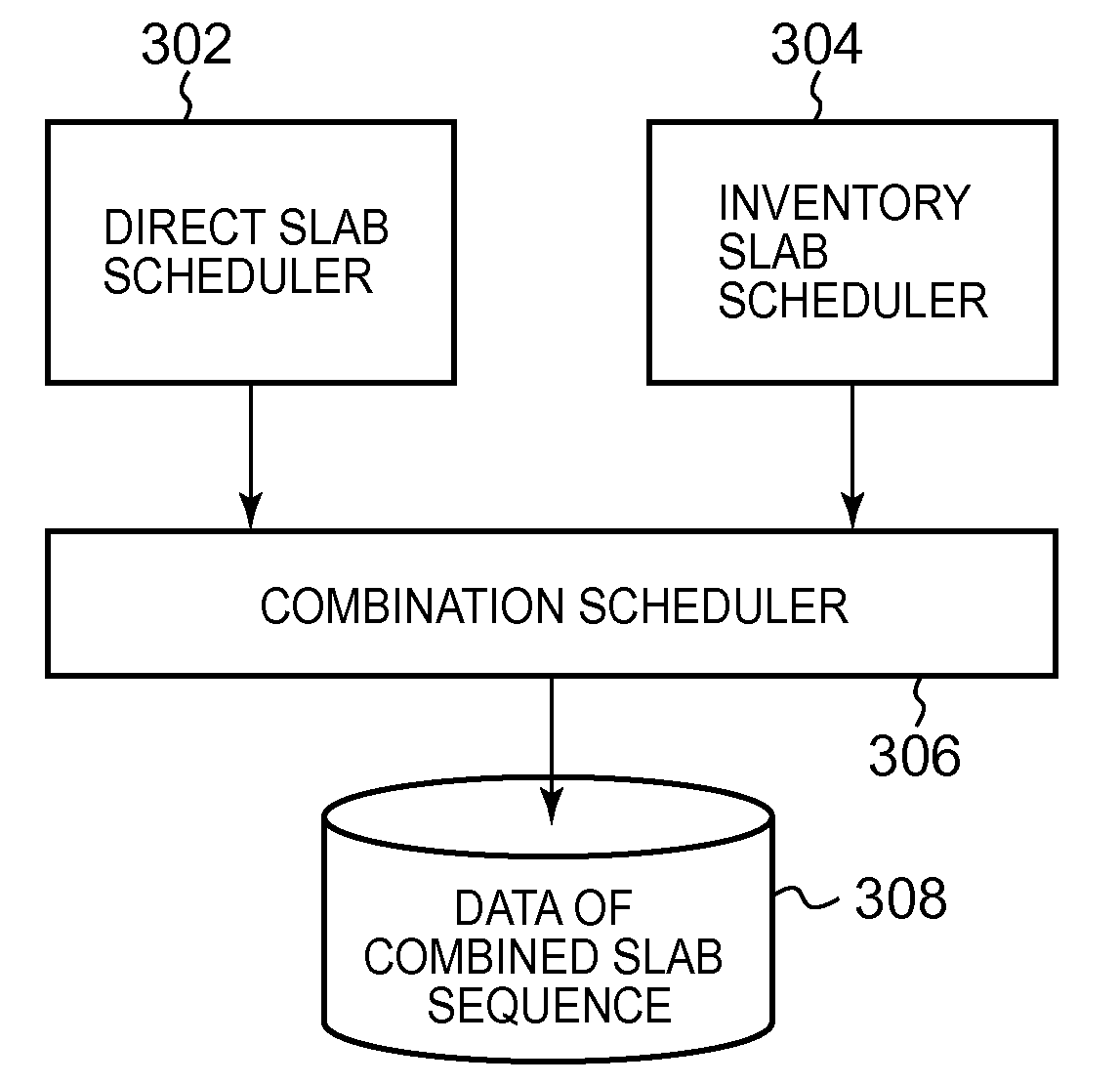
System, method and computer program product for combined scheduling of two different slab sequences by a rational technique. A two-dimensional grid graph having a direct slab sequence as a first dimension and an inventory slab sequence as a second dimension is prepared by processing of a computer as a data structure represented on a memory or a hard disk drive of the computer. A processing program of the computer generates two child nodes corresponding to a direct slab and an inventory slab, in each node of the two-dimensional graph according to a predetermined algorithm. By defining an appropriate weighting function, the processing program of the computer weights edges between nodes in the two-dimensional grid graph. After forming the weighted graph on a storage device of the computer such as the memory or the hard disk drive, the processing program of the computer calculates a path from a start point to an end point as a shortest path search problem.

Description

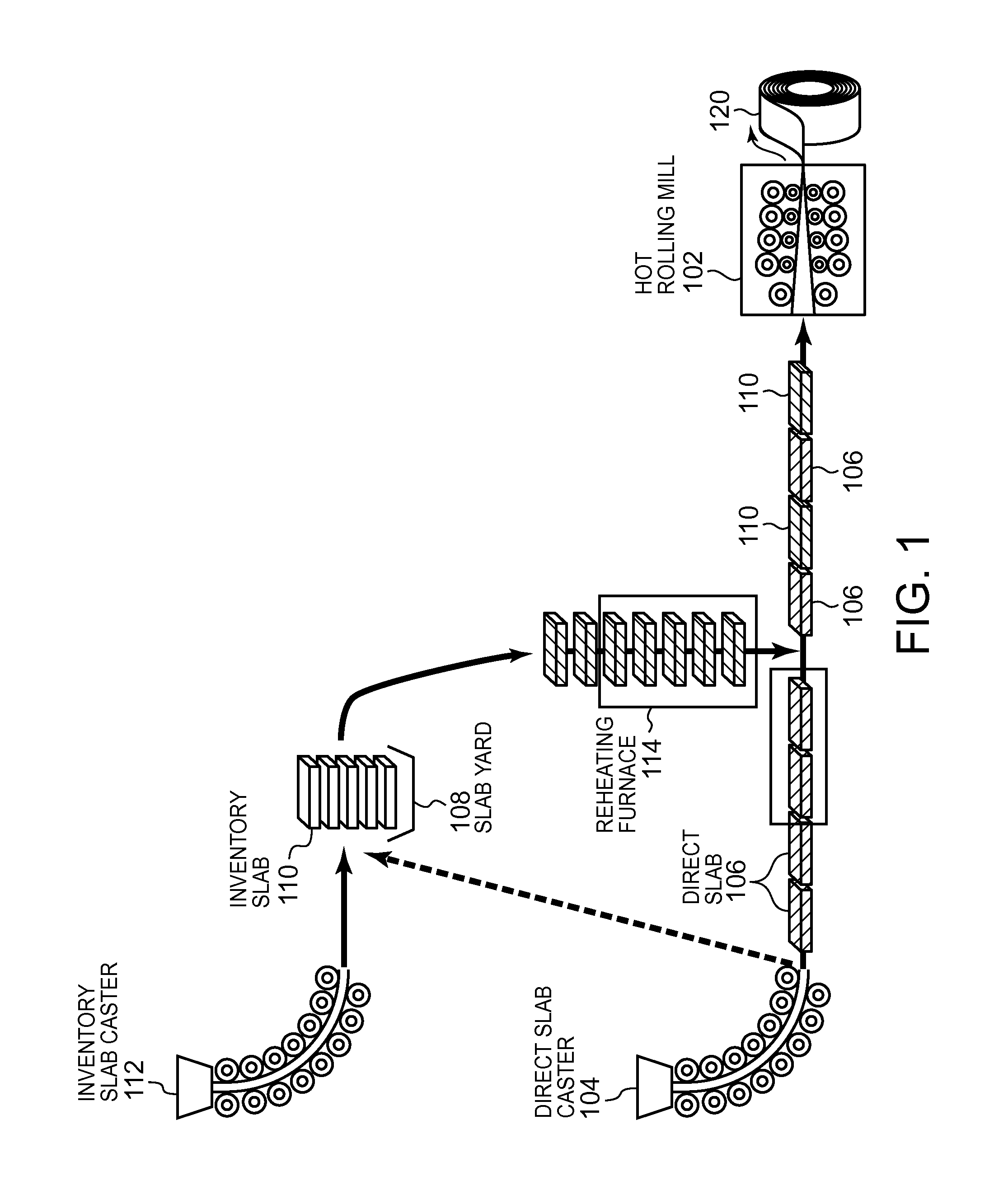
FIELD OF THE INVENTION[0001]The present invention relates to a technique of determining an arrangement order of a plurality of processing operations, and more particularly relates to a system, a method, and a program that determine a schedule for feeding thick steel plates called slabs to a hot rolling process by rollers.BACKGROUND ART[0002]Conventionally, ironworks produce steel plates of various thicknesses and sizes by a hot rolling process (also referred to as a hot strip mill process). The hot rolling process is a process of sandwiching a thick steel plate called a slab from above and below by rollers and stretching the slab to produce a thin plate called a coil.[0003]Surface quality of the coil thus produced depends on a surface state of the rollers. When a plurality of slabs are rolled one after another by the rollers, the surface state of the rollers deteriorates gradually. Therefore, a slab required to have high quality is desirably rolled while the rollers are still new.[0...

Claims


Application Information

Patent Timeline
Patent Type & Authority Applications(United States)
IPC IPC(8): G06F19/00
CPCB21B13/22B21B37/00B22D11/142B22D11/1206B22D11/12G05B19/41865G05B2219/32298G05B2219/32336Y02P90/02
Inventor HAMA, TOSHIYUKIYOSHIZUMI, TAKAYUKI
Owner IBM CORP
Learn More