
Method for determining data rate and packet length in mobile wireless networks

a mobile wireless and data rate technology, applied in the field of wireless networks, can solve the problems of increasing the length of the packet length, the channel cannot sustain efficient communication using large packets, and the difficulty of maintaining a high system performance in these networks

Active Publication Date: 2012-03-29
SYMBOL TECH LLC
View PDF4 Cites 11 Cited by
  • Summary
  • Abstract
  • Description
  • Claims
  • Application Information

AI Technical Summary

Problems solved by technology

Because the propagation conditions in mobile networks are time-varying and error-prone, it is challenging to sustain a high system performance in these networks.
At a reduced channel coherence time, the channel can not sustain efficient communication using large packets.
However, with a lower data rate, more symbols are needed for carrying the same amount of information, which increases the length of the packet length.
At high moving speed of objects, the very large data packet may take too long to be transmitted and the communication may not be sustainable by mobile channels, which in fact could result in poorer performance.
Therefore, increasing the energy per bit through change of data rate with the intent of improving mobile network efficiency can in fact deteriorate it.
Firstly, with regards to the correlation between data rate and packet length: the determination of data rate and packet length is constructed as a two-dimensional problem.
For a given channel condition, G becomes a function of L and D. So it is possible to construct an optimization model targeting the effective throughput G as function of L and D. By solving this optimization problem, one can obtain the values of L and D maximizing the value of effective throughput G. Although the optimization itself seems straightforward, it is difficult to achieve the prerequisite of the problem—channel condition (in terms of signal to noise ration (SNR) and environment).
Even more complicated than SNR, the environment that a wireless network operates on is almost impossible to measure.
While using a wireless device, one can observe that the same SNR, which generates good throughput in rural environment, results in poor performance in a complex environment such as city highway.
Although the three mentioned components of channel condition seem tangible, it is challenging to measure each of them.
Even if the receiver can measure the SNR, the only way that transmitter side would get it is through a report message, which adds significant overhead to the network.
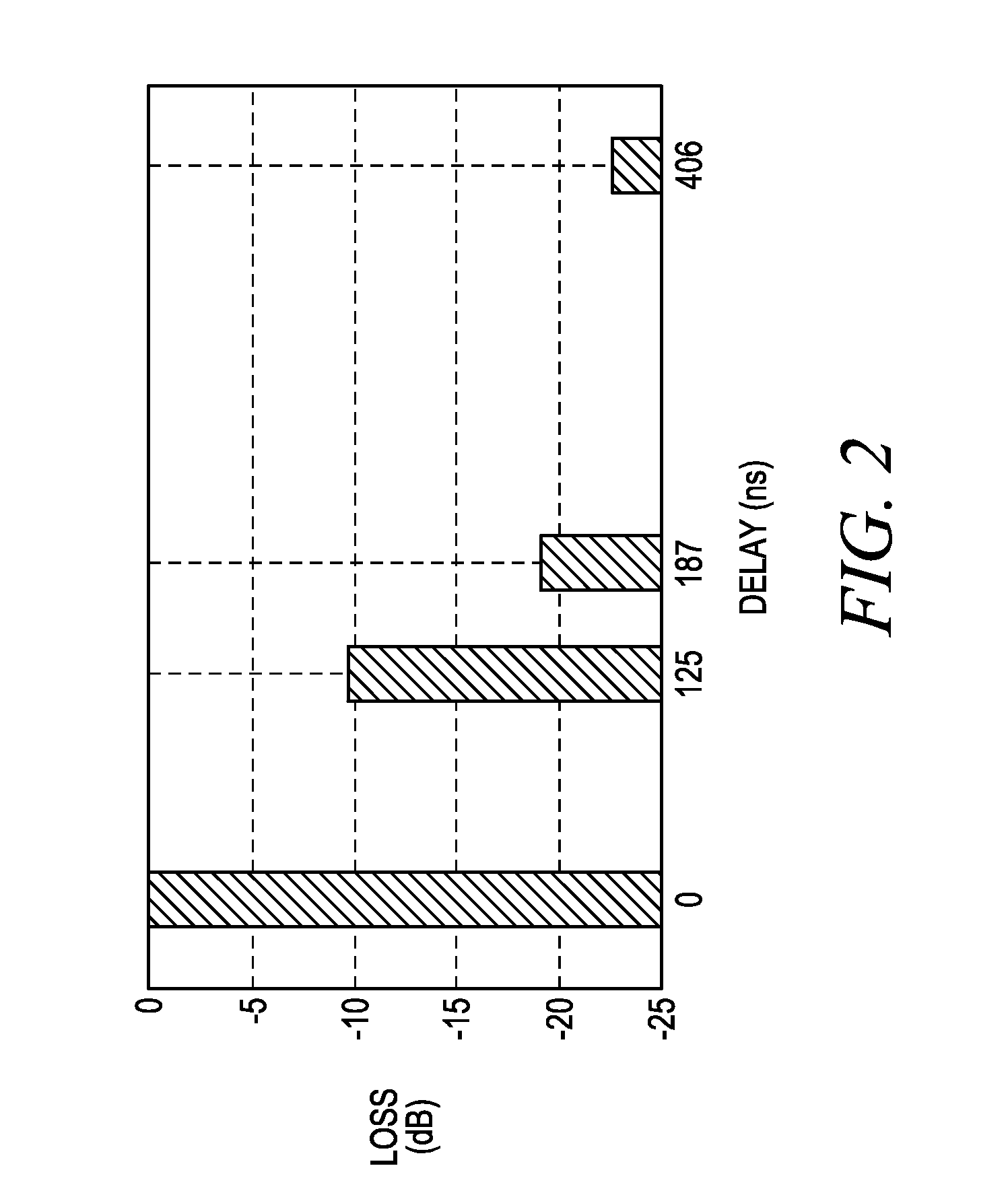
Generating a delay profile of the multipath environment is also a complex process.
Hence, when a wireless mobile device is communicating, it is impossible to directly detect the delay profile in real time.
However, it is hard for a wireless device to detect relative speed unless some special protocols and equipment like global positioning system (GPS) technology is deployed.
So it should account for the velocity of the wireless device's surrounding objects, which is extremely difficult to measure.
Due to the challenges of directly measuring these channel condition components, the current method utilizes channel condition estimations based on simulation.
However, since the channel condition is set up by varying SNR, multipath delay profile and velocity and the impact of these factors are not quantifiable, it is not clear how to quantify the channel condition and use it as a variable.
Therefore, if the number of data rates is large, such process could be computationally expensive.
Hence, the proposed method requires serious simulation effort.
So this method is only suitable for the networks and channel models that can be simulated.
If a wireless device experiences a channel that can not be described by any of the delay profiles we have simulated, the accuracy of the method will be degraded.
However, after years of effort on channel modeling, most of environment has been measured and described by delay profiles.
This could only induce oscillations of the parameter adjustments.

Method used


Image

  • Method for determining data rate and packet length in mobile wireless networks
  • Method for determining data rate and packet length in mobile wireless networks
  • Method for determining data rate and packet length in mobile wireless networks

Examples


Embodiment Construction

[0018]A method is described herein to determine optimal data rate and packet length in mobile networks. Unlike the adaptive, trial based or other suboptimal algorithms, this method directly determines the optimal packet length (L) and data rate (D), which allows fast convergence in the mobile channel. The method automatically identifies and quantifies channel conditions, as well as adjusts parameters according to changes of channel conditions.

[0019]In the method provided herein, an abstract variable (Channel condition Index (CCI)) is abstracted from simulations and this variable is then used to describe and quantify the impact of three components of channel conditions: signal-to-noise ratio (SNR), multipath environment and velocity. Based on packet completion rate (PCR) status, the channel condition is identified in terms of CCI value. Once CCI is identified, the model of effective throughput G is directly optimized to locate the best packet length (L) and data rate (D). Although th...


PUM


Abstract

A method is provided to determine optimal data rate and packet length in mobile networks. The method directly determines the optimal packet length (L) and data rate (D), which allows fast convergence in the mobile channel. The method automatically identifies and quantifies channel conditions, as well as adjusts parameters according to changes of channel conditions. A variable (Channel condition Index (CCI)) is abstracted from simulations and then used to describe and quantify the impact of three components of channel conditions: signal-to-noise ratio (SNR), multipath environment and velocity. Based on packet completion rate (PCR) status, the channel condition is identified in terms of CCI value. Once CCI is identified, the model of effective throughput G is directly optimized to locate the best packet length (L) and data rate (D).

Description

FIELD OF THE DISCLOSURE[0001]The present disclosure relates generally to wireless networks and more particularly to determining data rate and packet length in mobile wireless networks.BACKGROUND[0002]Wireless communication networks, such as mobile wireless telephone networks, have become increasingly prevalent over the past decade. The wireless telephone networks are commonly referred to as “cellular networks”, because the network infrastructure is arranged to divide the service area into a plurality of regions called “cells”. A terrestrial cellular network includes a plurality of interconnected base stations, or base nodes, that are distributed geographically at designated locations throughout the service area. Each base node includes one or more transceivers that are capable of transmitting and receiving electromagnetic signals, such as radio frequency (RF) communications signals, to and from mobile user nodes, such as wireless telephones, located within the coverage area. The com...

Claims


Application Information

Patent Timeline
IPC IPC(8): H04L12/26
CPCH04W28/06H04L1/0007H04W28/22
Inventor CHU, YUECHUNBELCEA, JOHN M.JOSHI, AVINASH
Owner SYMBOL TECH LLC
Learn More