
Liquid crystal display device

a liquid crystal display and display device technology, applied in non-linear optics, instruments, optics, etc., can solve the problems of slow response speed and dark lines generated, and achieve the effect of suppressing the reduction of transmittance, reducing the deterioration of contrast characteristics, and controlling the alignment of liquid crystal molecules more reliably

Inactive Publication Date: 2012-03-29
SHARP KK
View PDF3 Cites 6 Cited by
  • Summary
  • Abstract
  • Description
  • Claims
  • Application Information

AI Technical Summary

Benefits of technology

[0021]According to the liquid crystal display device of the present invention, alignment of liquid crystal molecules can be controlled more reliably and the deterioration of the contrast characteristics and reduction in transmittance can be suppressed without complicating the manufacturing process of the matrix substrate.

Problems solved by technology

The main cause of this problem is dark lines generated in areas above the protrusion and / or the slits, which are borders of alignment divisions.
As a result, it takes longer time for the alignment to stabilize after the prescribed voltage is applied on the liquid crystal layer, which slows down the response speed.

Method used


Image

  • Liquid crystal display device
  • Liquid crystal display device

Examples


Embodiment Construction

[0023]In this specification, the 3 o'clock direction, 12 o'clock direction, 9 o'clock direction, and 6 o'clock direction when the display surface of the liquid crystal display device is observed in a plan view are defined as 0° direction, 90° direction, 180° direction, and 270° direction, respectively.

[0024]Below, although embodiments are described to explain the present invention further in detail with reference to figures, the present invention is not limited to these embodiments.

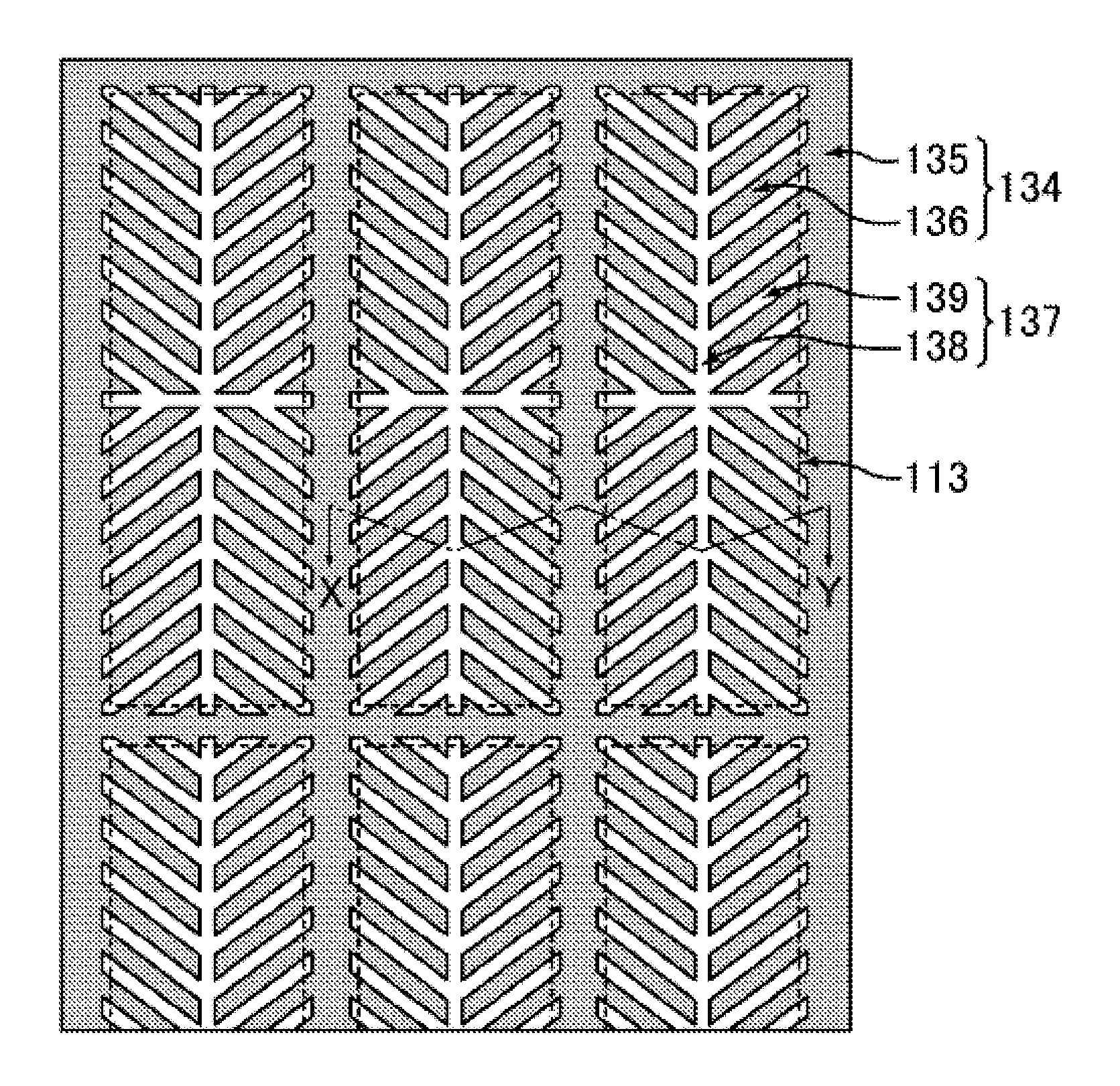
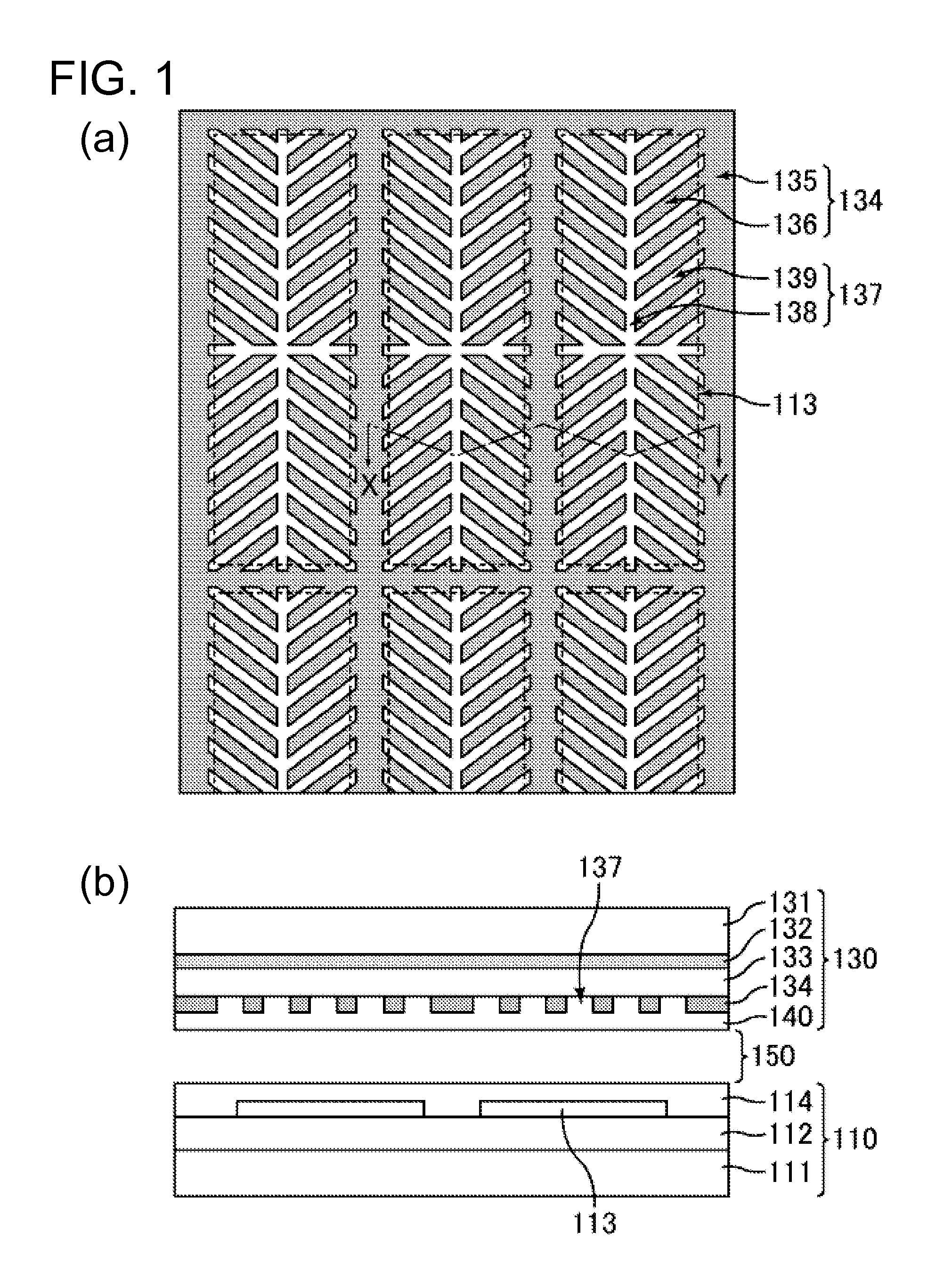
[0025]As shown in FIG. 1, the liquid crystal display device of the present embodiment is a vertical alignment mode liquid crystal display device having a matrix substrate 110 disposed on the back side, an opposite substrate 130 disposed on the viewer's side and is bonded to the matrix substrate 110 with a sealing member, and a liquid crystal layer 150 sealed in the space between the matrix substrate 110 and the opposite substrate 130. The matrix substrate 110 and the opposite substrate 130 are held apart ...


PUM


Abstract

The present invention provides a liquid crystal display device that can control the alignment of liquid crystal molecules more reliably and also can suppress the deterioration of the contrast characteristics and a reduction in transmittance without complicating the manufacturing process of a matrix substrate. Specifically disclosed is a liquid crystal display device including a pair of substrates (110 and 130) and a liquid crystal layer held between the pair of substrates. One of the pair of substrates has pixel electrodes (113). The other of the pair of substrates has a first opposite electrode (132), an insulating layer (133) formed on the first opposite electrode, and a second opposite electrode (134) formed on the insulating layer. The second opposite electrode has an opening (137), and the opening overlaps at least with a pixel when the pair of substrates are observed in a plan view, and the first opposite electrode overlaps at least with part of said opening in the pixel when the pair of substrates are observed in a plan view.

Description

TECHNICAL FIELD[0001]The present invention relates to a liquid crystal display device. More particularly, the present invention relates to a liquid crystal display device suitable as a mid- and small-sized liquid crystal display device.BACKGROUND ART[0002]Multi-domain vertical alignment mode liquid crystal display devices (hereinafter referred to as “MVA-LCD”) are known. In this type of display device, liquid crystal molecules having negative dielectric constant anisotropy are vertically aligned, and alignment control structures, which are ridges (linear protrusions) on the substrate and / or openings (slits) in the electrode, are provided. Because an MVA-LCD includes alignment control structures, liquid crystal alignment upon voltage application can still be controlled in multiple directions even if rubbing treatment is not performed. Also, MVA-LCDs are superior to conventional TN (Twisted Nematic) type LCDs in the viewing angle characteristics.[0003]However, conventional MVA-LCDs on...

Claims


Application Information

Patent Timeline
IPC IPC(8): G02F1/1343
CPCG02F1/133707G02F1/133753G02F2201/122G02F2201/121G02F1/134309
Inventor KAISE, YASUYOSHITASAKA, YASUTOSHI
Owner SHARP KK
Learn More