
Control system for extraction of hydrocarbons from underground deposits

a control system and hydrocarbon extraction technology, applied in the direction of design optimisation/simulation, well accessories, borehole/well accessories, etc., can solve the problems of difficult to sense the real-time conditions of the deposit and the well bore, and the inability to drill and refine the methods used in extracting standard crude oil, etc., to achieve the effect of facilitating the fluid flow of a resour

Active Publication Date: 2012-03-29
HARRIS CORP
View PDF1 Cites 27 Cited by
  • Summary
  • Abstract
  • Description
  • Claims
  • Application Information

AI Technical Summary

Benefits of technology

[0005]A control system for use in extracting hydrocarbons from an underground deposit is disclosed that comprises an electromagnetic heating system and a processor. The electromagnetic heating system is configured to heat the underground deposit to facilitate fluid flow of a resource for extraction from the underground deposit. The processor is configured to control the electromagnetic heating system in response to temperature data and pressure data for th...

Problems solved by technology

Because of the high viscosity of bituminous ore, oil sands, oil shale, tar sands, and heavy oil, the drilling and refinement methods used in extracting standard crude oil are typically not available.
During in-situ processing, it is difficult to sense the real-time conditions in the deposit and the well bore.
Uncertainty often exists about whether the hydrocarbons are indeed flowing.
Valuable time and heat energy are wasted in unsuccessful attempts at in-situ processing when low formation permeability conditions prevent diffusion of steam and limit heating, or when steam and heat move away from a zone that is targeted for heating through formation fractures or through high permeability materials.
However, these measurements do not produce a near real-time picture of conditions in the formation.

Method used


Image

  • Control system for extraction of hydrocarbons from underground deposits
  • Control system for extraction of hydrocarbons from underground deposits
  • Control system for extraction of hydrocarbons from underground deposits

Examples


Embodiment Construction

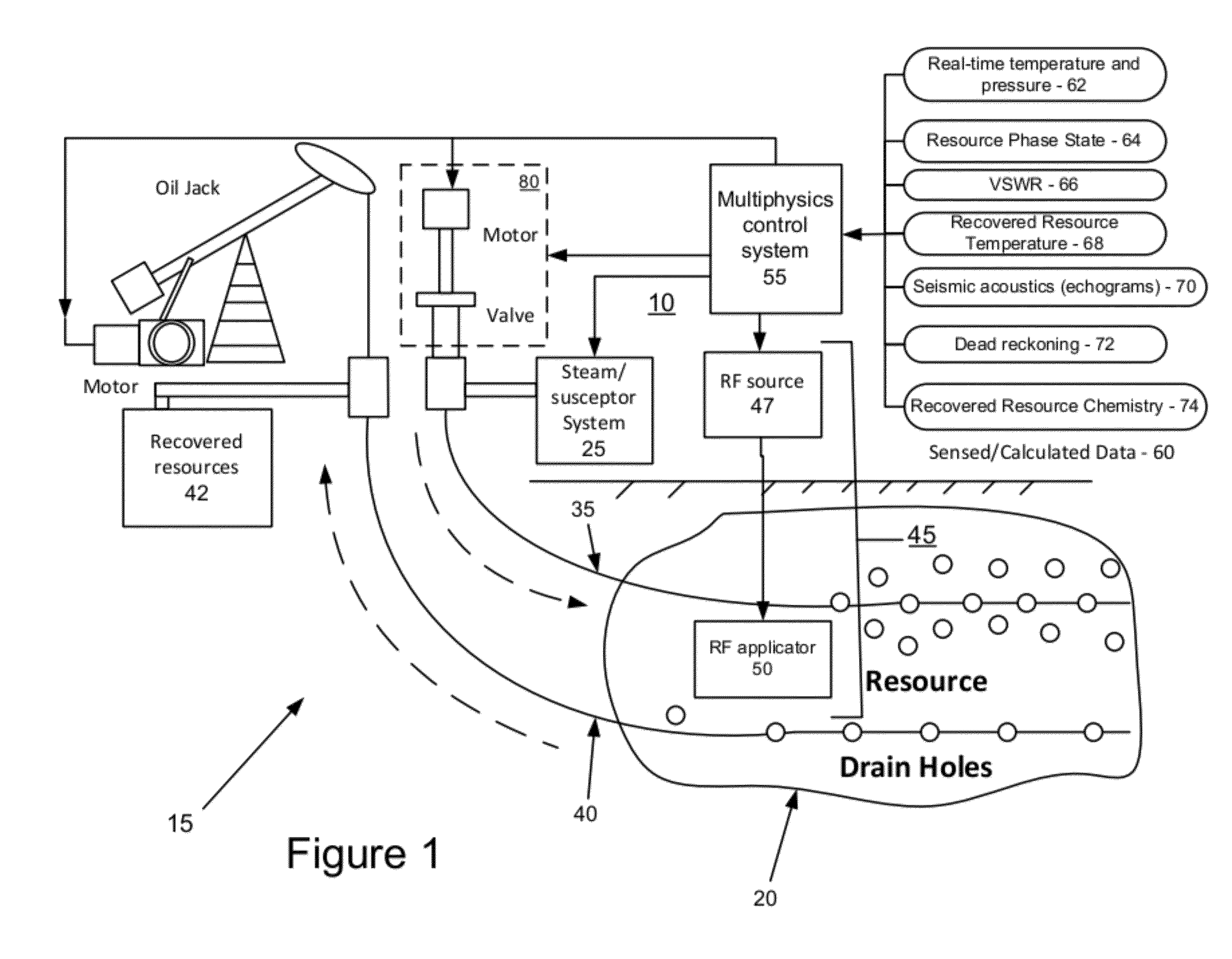
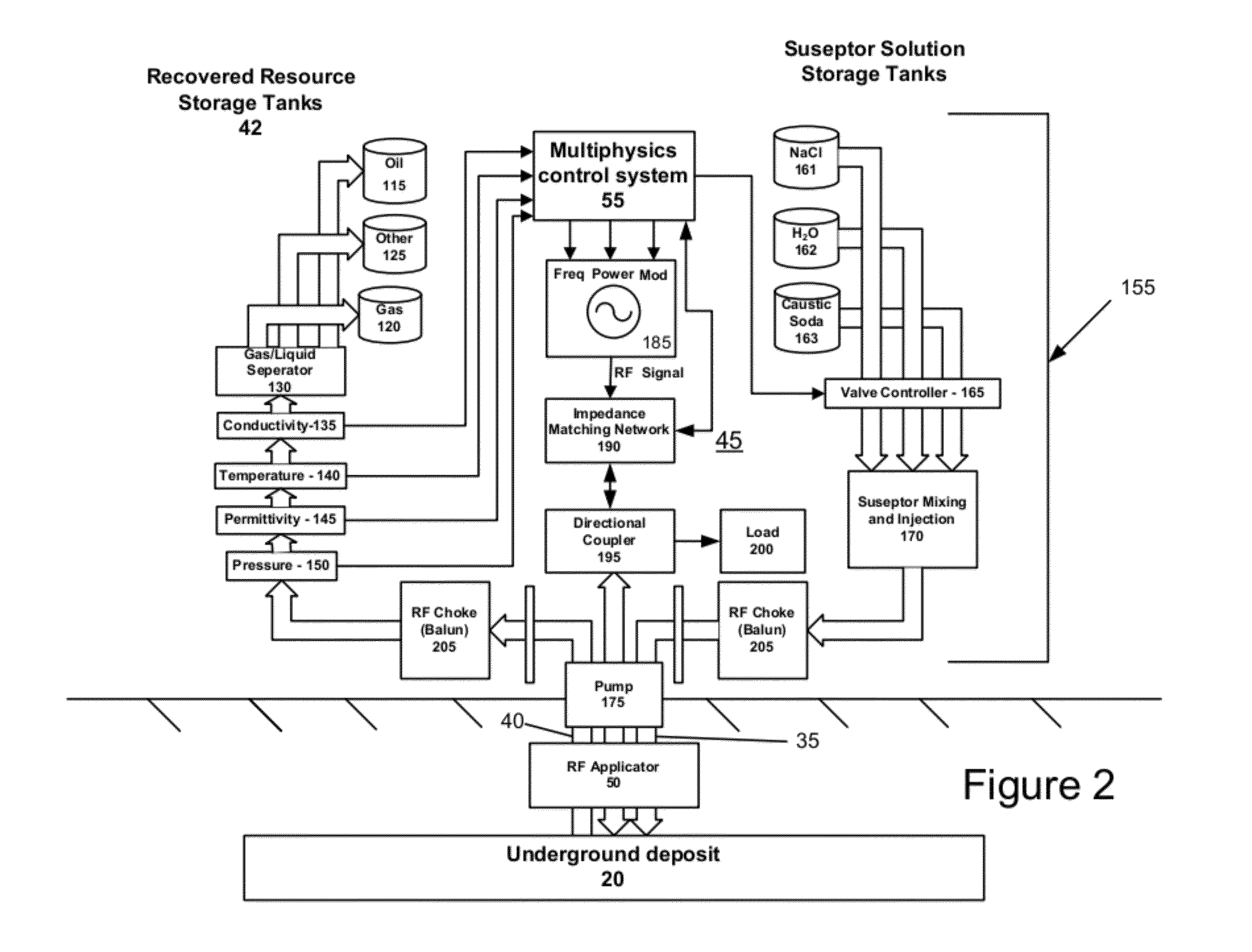
[0017]FIG. 1 illustrates one embodiment of a steam assisted gravity drainage system 15 for in-situ extraction of hydrocarbons from an underground deposit 20. As shown, steam assisted gravity drainage system 15 includes a control system 10 that controls the operation of the various components of the system. Steam and other suitable susceptors for the steam assisted gravity drainage system 15 are provided by a steam and susceptor system 25. The steam and susceptors are injected from the steam and susceptor system 25 through a delivery pipe 35 and into the underground deposit 20. The steam and susceptor heat the materials in the underground deposit 20 to a temperature at which hydrocarbons in the formation, condensed steam, and possibly other liquids drain down to a recovery pipe 40 where they are pumped out as recovered resources into storage tanks 42 for storage and processing. Although control system 10 is described in the context of the steam assisted gravity drainage system 15, it...


PUM


Abstract

A control system for use in extracting hydrocarbons from an underground deposit is disclosed that comprises an electromagnetic heating system and a processor. The electromagnetic heating system is configured to heat the underground deposit to facilitate fluid flow of a resource for extraction from the underground deposit. The processor is configured to control the electromagnetic heating system in response to temperature data and pressure data for the underground deposit. The processor correlates the temperature data and pressure data with predetermined water phase characteristics to control the electromagnetic heating system so that substantially all water in the underground deposit is maintained in a liquid state. The control system may also generate voxel data corresponding to spatial characteristics of the underground deposit. The spatial characteristics may be presented as a map on a display.

Description

STATEMENT REGARDING FEDERALLY SPONSORED RESEARCH OR DEVELOPMENT[0001][Not Applicable]BACKGROUND OF THE INVENTION[0002]As the world's standard crude oil reserves are exhausted, and the continued demand for oil causes oil prices to rise, oil producers are trying to increase their output of hydrocarbons from bituminous ore, oil sands, tar sands, and heavy oil deposits. These materials are often found in naturally occurring mixtures of sand or clay. Because of the high viscosity of bituminous ore, oil sands, oil shale, tar sands, and heavy oil, the drilling and refinement methods used in extracting standard crude oil are typically not available. Therefore, recovery of oil from these deposits requires heating to separate hydrocarbons from other geological materials and to preserve hydrocarbons at temperatures at which they will flow. Steam is typically used to provide this heat, although electric and radio frequency heating is sometimes employed. The heating and processing can take place...

Claims


Application Information

Patent Timeline
IPC IPC(8): E21B43/00
CPCE21B36/04G06F17/5009E21B43/2408E21B43/2401G06F30/20
Inventor PARSCHE, FRANCIS E.DANIEL, DAVID M.
Owner HARRIS CORP
Learn More