
Method for positioning an instrument

Inactive Publication Date: 2012-03-22
STELLENBOSCH UNIVERSITY
View PDF4 Cites 8 Cited by
  • Summary
  • Abstract
  • Description
  • Claims
  • Application Information

AI Technical Summary

Benefits of technology

[0016]It is an object of this invention to provide a method for positioning an instrument for ins

Problems solved by technology

Despite the fact that the details of these techniques are meticulously described, gaining correct access to a pre-identified area of a calyx is usually the most difficult part of PCNL.
It often results in multiple needle punctures and repeated radiological screening which entails those present receiving prolonged doses of X-rays.
For the patient this may not be too serious, but for those performing such procedures regularly this is undesirable.
Also, “correct access” is not always obtained and urologists often end up accepting sub-optimal positions of access.
Some of these techniques, such as CT and MRI are overly expensive and can only be implemented in highly equipped facilities.
Many of the techniques described above are not utilized in practice due to high cost of the automated systems that are required and the need for specialized imaging equipment.

Method used


Image

  • Method for positioning an instrument
  • Method for positioning an instrument
  • Method for positioning an instrument

Examples


Embodiment Construction

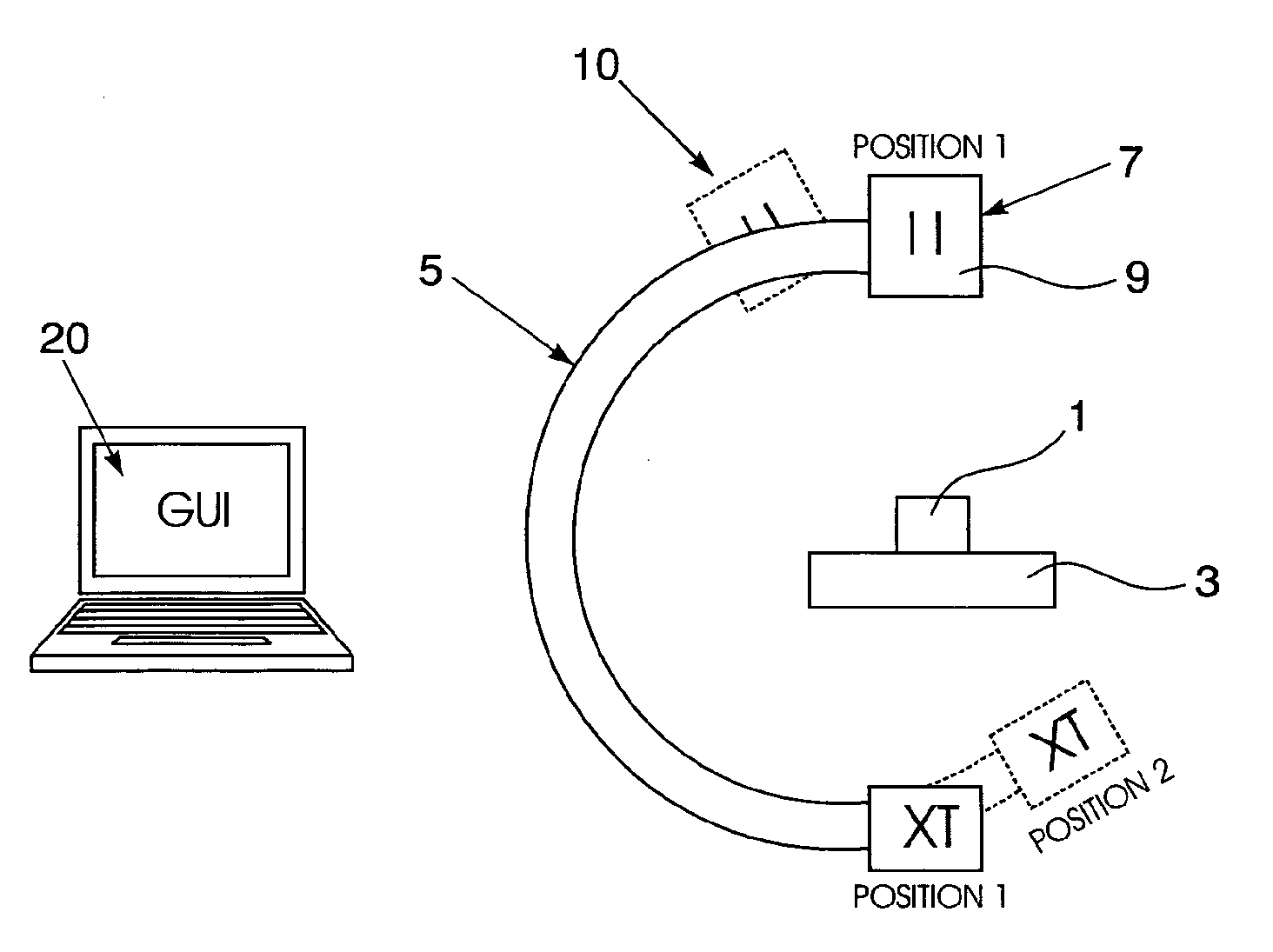
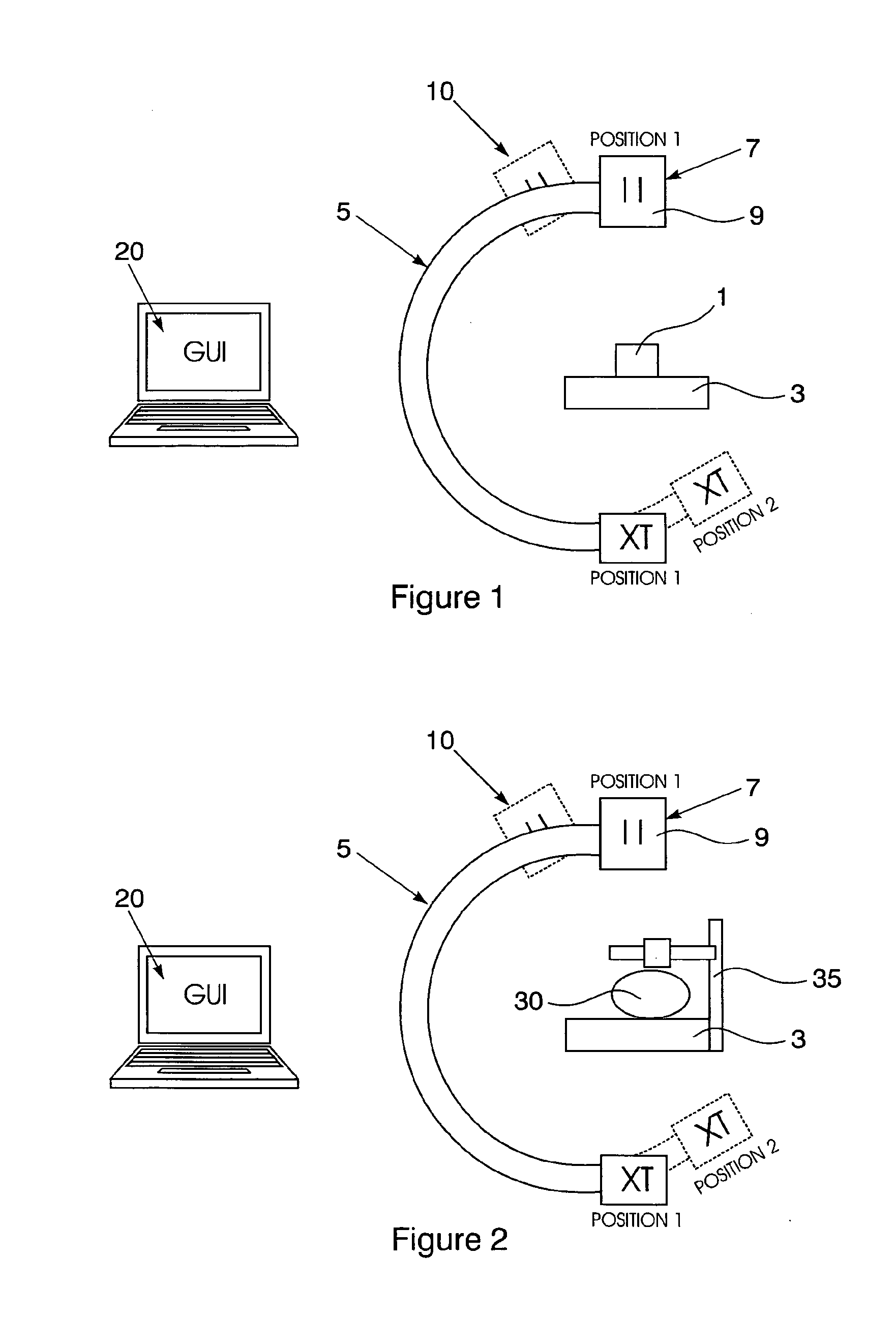
[0039]A method of positioning an instrument, in this embodiment a needle, is illustrated with reference to FIGS. 1 and 2. In a first step, illustrated in FIG. 1, a calibration object (1) is placed on an operating table (3) and a C-arm fluoroscope (5) used to take two images thereof. In this embodiment, the first image is taken from a first orientation (7) with the x-ray generator (9) directly overhead. The second image is taken from a second orientation (10) with the x-ray generator (shown in broken lines) rotated 20° from the first orientation.

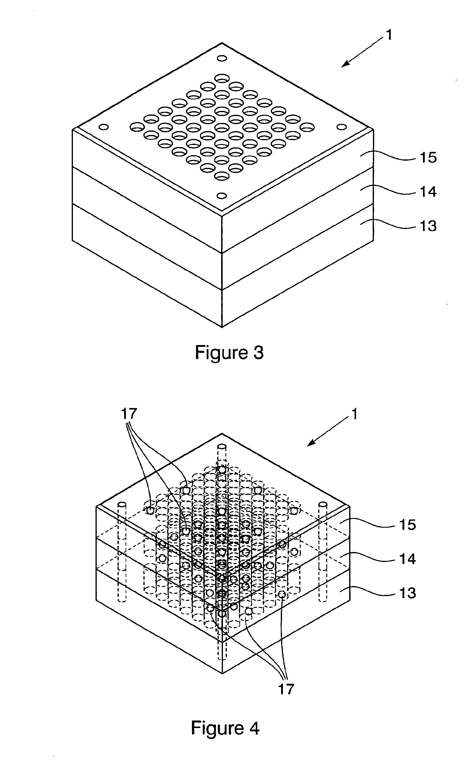
[0040]As shown in FIGS. 3 and 4, the calibration object (1) is box shaped and has three super adjacent layers (13, 14, 15), each of which has a plurality of radio opaque markers (17) arranged at a known location in a planar array. The markers (17) are furthermore arranged so that each is visible in the fluoroscopic images taken from both the first orientation and second orientation. The location of each marker (17) is pre-determined and in th...


PUM


Abstract

A method of positioning a surgical instrument is provided which includes mapping a volume adjacent an operating table by taking mapping images from two orientations of a calibration object which includes a 3-dimensional array of radio opaque markers in a known configuration. A patient is positioned on the operating table with a patient target area within a mapped volume, and an instrument holder carrying a known configuration of radio opaque markers positioned adjacent the target area. Further fluoroscopic target images of the target area and instrument holder are obtained from the two orientations and the target area then reconstructed in 3-dimensions by comparing the target images to the mapping images. An instrument holder orientation is then calculated from the reconstruction.

Description

FIELD OF THE INVENTION[0001]This invention relates to a method for positioning an instrument for insertion into a patient.BACKGROUND TO THE INVENTION[0002]Percutaneous nephrolithotomy (PCNL), first described in 1976 by Fernstrom and Johansson, is a minimally invasive surgical procedure aimed at removing problematic kidney stones. Advances in surgical technique and technology over the past 30 years have allowed urologists to remove stones percutaneously with increasing efficiency. As the percutaneous route to stone removal is superior to the open approach in terms of morbidity, convalescence, and cost, PCNL has replaced open surgical removal of large or complex calculi at most institutions.[0003]One of the steps in the PCNL procedure entails obtaining kidney calyx access to make the insertion of dilators and stone removal equipment possible. This access is usually obtained using one of two antegrade bi-planar fluoroscopy needle guidance techniques, namely “triangulation” and “eye of ...

Claims


Application Information

Patent Timeline
IPC IPC(8): H05G1/28
CPCA61B6/12A61B6/4441A61B6/466A61B6/583A61B2019/5289A61B19/54A61B2017/00725A61B2019/5238A61B19/201A61B2090/364A61B2090/376A61B90/11A61B90/39A61B6/04
Inventor SCHEFFER, CORNELIUSCONRADIE, JEAN-PIERREZARRABI, AMIR DAVIDSCHREVE, KRISTIAAN
Owner STELLENBOSCH UNIVERSITY
Learn More