
Display device

a technology of a display device and a switch board, which is applied in the direction of lighting support devices, electric apparatus casings/cabinets/drawers, instruments, etc., can solve the problems of difficult to set the optimum arrangement position and the amount of projection of the rotary encoder, so as to reduce the restriction on the effect of increasing flexibility in the arrangement position of the switch board

Inactive Publication Date: 2012-03-22
MITSUBISHI ELECTRIC CORP
View PDF9 Cites 7 Cited by
  • Summary
  • Abstract
  • Description
  • Claims
  • Application Information

AI Technical Summary

Benefits of technology

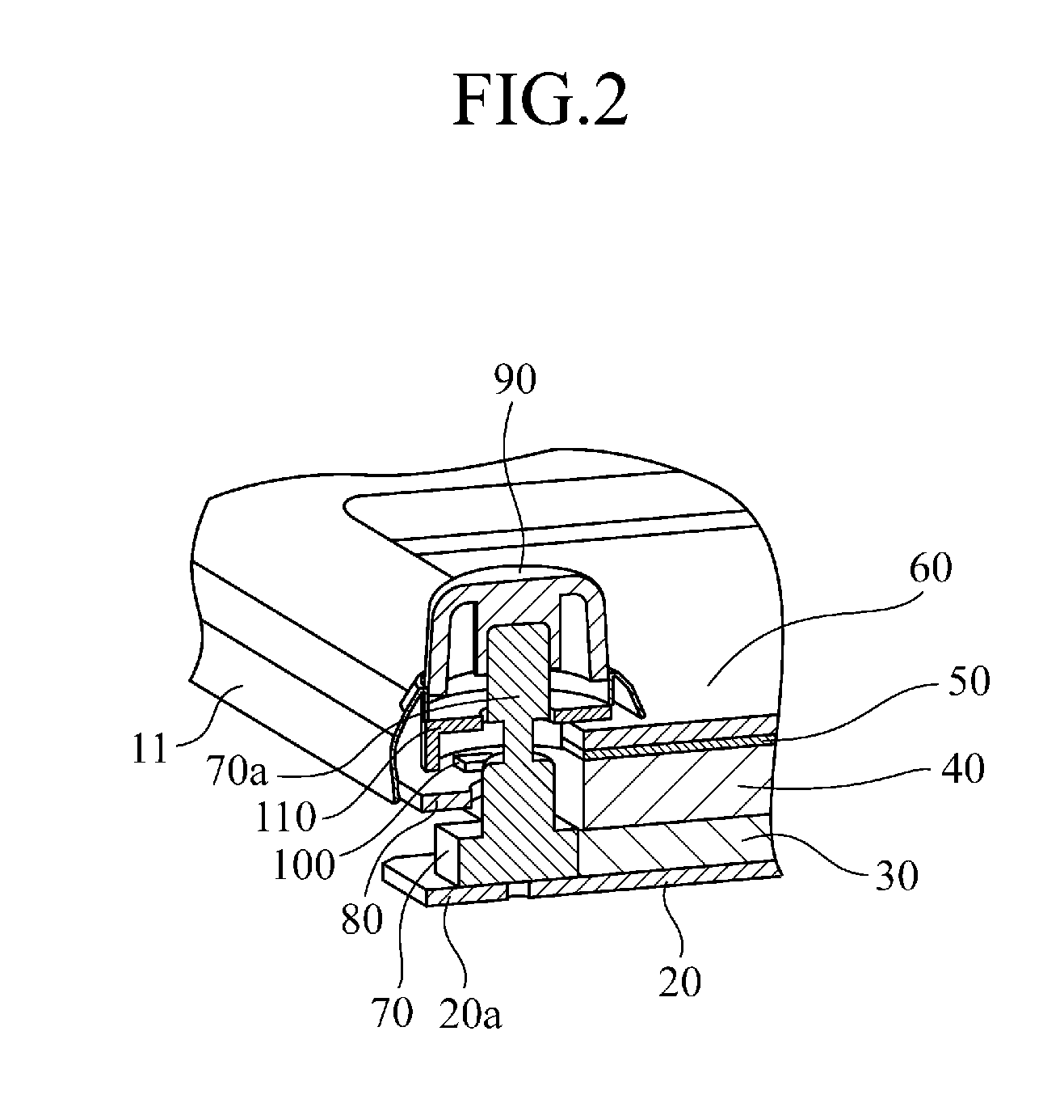
[0012]According to the display device of the invention, it is arranged that within the panel formed of the front panel and the rear panel, the switch board is disposed in proximity to the front panel, the display board is disposed in proximity to the rear panel, and the rotary encoder is disposed on the display board. Thus, there is provided an advantageous effect that enables to suppress the amount of projection of the rotary encoder from the front panel. Further, the arrangement position in depth of the switchboard is unaffected by the placement of the rotary encoder, and thus the restrictions on the arrangement position of the switchboard can be reduced. As a result, there is provided an advantageous effect of increasing flexibility in the arrangement position of the switch board.

Problems solved by technology

However, the amount of projection of the operation knob, attached to the shaft of the rotary encoder, from the front panel is regulated by a law in European region from the viewpoint of safety; thus, there is a problem such that according to the construction of the conventional display device, the above amount of projection raises an issue.
Further, the arrangement position in depth of the switchboard is set, in consideration of the amount of projection of the rotary encoder from the front panel, the illumination range and evenness of lighting for the switches, and the operation feeling of a push switch, resulting in a large number of restrictions; thus, there is a problem such that it is difficult to set the optimum arrangement positions thereof.

Method used


Image

  • Display device
  • Display device
  • Display device

Examples


first embodiment

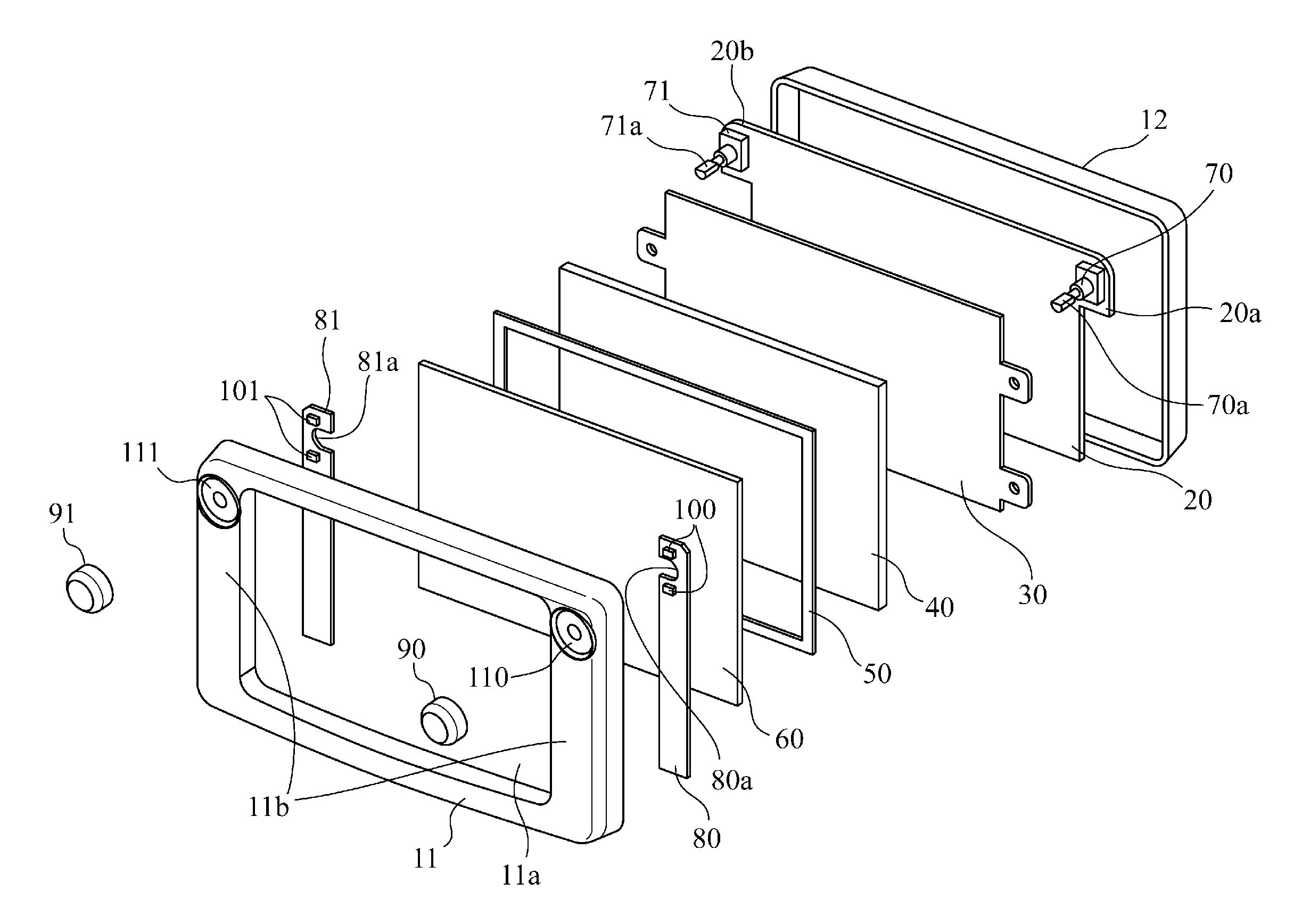
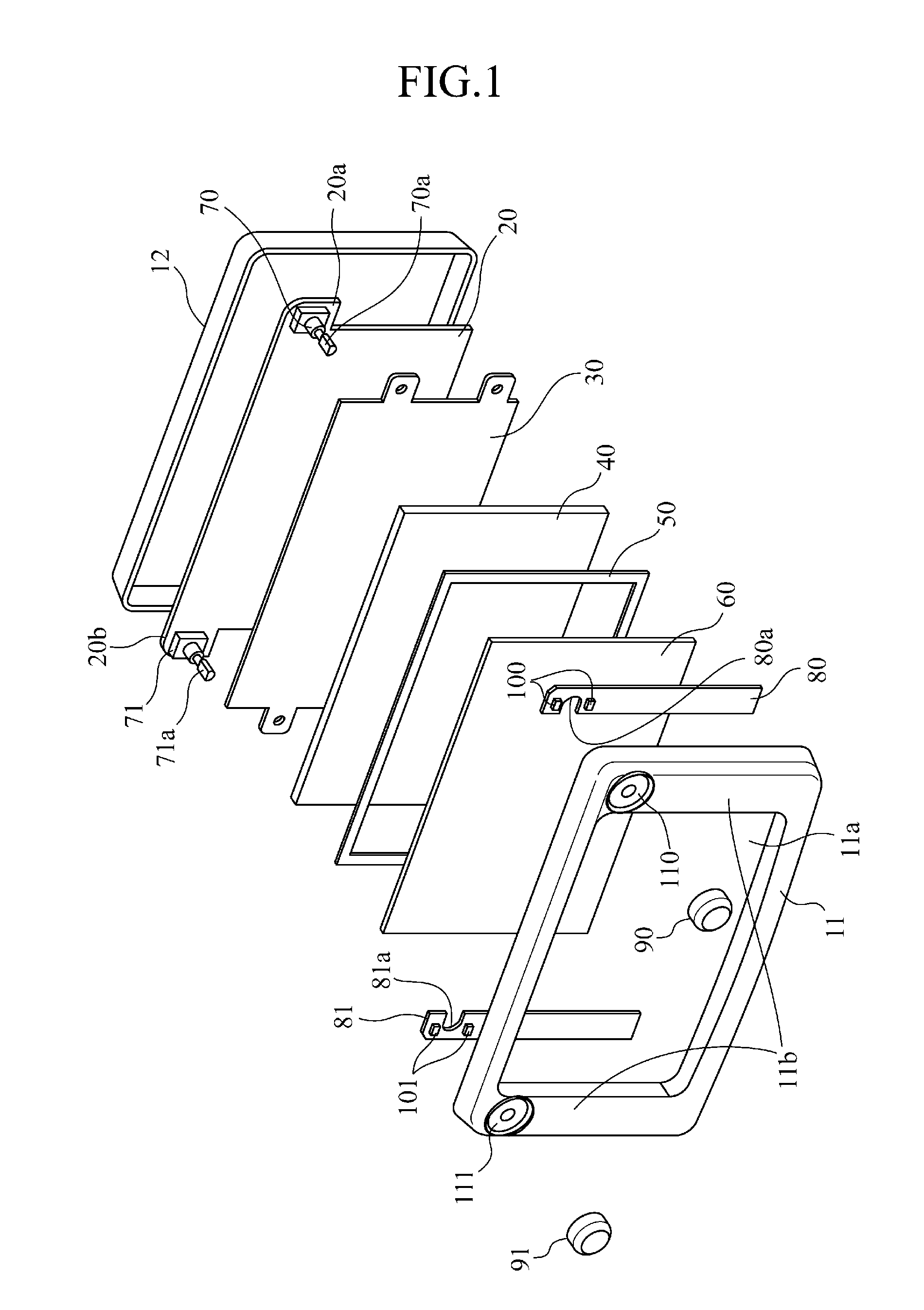
[0017]The configuration of a display device according to a first embodiment will now be discussed with reference to FIG. 1 and FIG. 2.

[0018]For example, as shown in FIG. 1, the display device is composed of: a front panel 11; a rear panel 12; a display board 20; a display board holder 30; a display 40; a touch panel holder 50; a touch panel 60; rotary encoders 70, 71; switch boards 80, 81; operation knobs 90, 91; light sources 100, 101; and prisms 110, 111.

[0019]The front panel 11 and the rear panel 12 support the internal components as a chassis of the display device, the front panel 11 is formed of a frame having an opening 11a working as a display unit, and various switches are disposed on the surface of the two sides 11b of the frame. For example, the display board 20, the display board holder 30, the display 40, the touch panel holder 50, and the touch panel 60 are disposed on the back of the opening 11a. Further, the rotary encoders 70, 71, the switch boards 80, 81, the light ...


PUM


Abstract

A display device includes, within a panel formed of a front panel 11 and a rear panel 12, a switchboard 80 disposed in proximity to the front panel 11; a display board 20 disposed in proximity to the rear panel 12; a display 40 disposed between the switch board 80 and the display board 20; a switch mounting section 20a formed by protruding laterally at least a portion of the display board 20 from the display 40; a rotary switch 70 attached to the switch mounting section 20a; and an operation knob 90 attached to a shaft of the rotary switch 70 extended through the switch board 80 and the front panel 11.

Description

TECHNICAL FIELD[0001]The present invention relates to a display device having a rotary encoder, for example.BACKGROUND ART[0002]In a display device, a panel constituted by a front panel and a rear panel, for instance, includes a switch board disposed in proximity to the front panel and a display board disposed in proximity to the rear panel. A pressure type of push switch and / or a rotary type of rotary encoder are disposed on the switch board, and a button of the push switch and / or an operation knob attached to a shaft of the rotary encoder are protruded on the surface of the front panel.[0003]Also, for the switches, there is disclosed a technology in which a user can easily see the switch even in a dark place. For example, according to Patent Document 1, an LED (Light Emitting Diode) as a light source for switch illumination is provided on a switch board, and the light from the LED illuminates a button through the back thereof.[0004]In a display device, when a switch in Patent Docu...

Claims


Application Information

Patent Timeline
Patent Type & Authority Applications(United States)
IPC IPC(8): H05K5/00F21V21/00
CPCG06F1/1601H04N5/64B60K2350/104B60K2350/102B60K2350/1024B60K37/06B60K35/10B60K2360/126B60K2360/143B60K2360/145
Inventor HIROTA, HIDEYUKI
Owner MITSUBISHI ELECTRIC CORP
Learn More