Quenching device and quenching method

a technology of a quenching device and a quenching method, which is applied in the direction of heat treatment equipment, manufacturing tools, furnaces, etc., can solve the problem that leakage problems are necessarily presen

Inactive Publication Date: 2012-03-22
ROBERT BOSCH GMBH
View PDF6 Cites 2 Cited by
  • Summary
  • Abstract
  • Description
  • Claims
  • Application Information

AI Technical Summary

Benefits of technology

[0006]The exemplary embodiments and / or exemplary methods of the present invention are based on an object of providing a quenching device in which leakage problems are avoided and in which a starting of the powerful drive motor for the blower is possible even before the flooding of the chamber with quenching gas, in particular when there is a vacuum in the chamber. In addition, an object of the exemplary embodiments and / or exemplary methods of the present invention is to indicate a method that enables operation of the blower drive motor independent of the atmosphere in the chamber in which the blower wheel is situated.
[0008]The exemplary embodiments and / or exemplary methods of the present invention recognize that operation of the drive motor (which may be fashioned as a standard electric motor) for the at least one blower wheel independent of the atmosphere and pressure conditions in the chamber accommodating the blower wheel is possible only if the drive motor is situated outside this chamber. Because in the prior art the motor shaft of the drive motor passes through the wall of the chamber, problems with leakage are necessarily present in the prior art. In order to avoid this problem, the exemplary embodiments and / or exemplary methods of the present invention provides that the drive motor be coupled to the blower wheel not mechanically, as in the prior art, but rather in contactless fashion. In other words, the drive motor and the blower wheel are provided with a coupling that is fashioned such that this coupling is capable of transmitting, without contact, a torque from the drive motor to the blower wheel. In this way, it is not necessary for mechanical components of the drive train to pass through the wall of the chamber, thus avoiding leakage problems.
[0009]The situation of the drive motor outside the chamber that can be flooded with quenching gas and in which a vacuum may be produced additionally makes it possible to start up the powerful drive motor before the chamber is flooded with quenching gas, which may be early enough that the drive motor has already reached its nominal rotational speed at the beginning of the actual quenching process, i.e., as a rule, when the chamber is completely flooded with quenching gas. A further advantage of the quenching device designed in this way is that it is not necessary to use specially sealed motors; rather, comparatively inexpensive standard electric motors may be used. A specific embodiment of the quenching device quite particularly may be used in which the coupling by which a drive torque can be transmitted from the drive motor to the blower wheel is fashioned as a magnetic coupling capable of transmitting torque through the wall of the chamber.
[0017]The present invention is also directed to a method for quenching material to be quenched, in particular metallic workpieces, with quenching gas using a quenching device, which may be a quenching device as described above. In the method, the blower wheel is used to accelerate the quenching gas in order to realize a good heat transmission between the material being quenched and the quenching gas. The core of the method of the present invention is that the blower wheel is driven by the drive motor in contactless fashion, in particular using a magnetic coupling. This specific embodiment makes it possible to transmit the torque through a wall and thus to situate the drive motor outside the chamber in which the blower wheel is situated.

Problems solved by technology

Because in the prior art the motor shaft of the drive motor passes through the wall of the chamber, problems with leakage are necessarily present in the prior art.

Method used


Image

  • Quenching device and quenching method
  • Quenching device and quenching method

Examples


Embodiment Construction

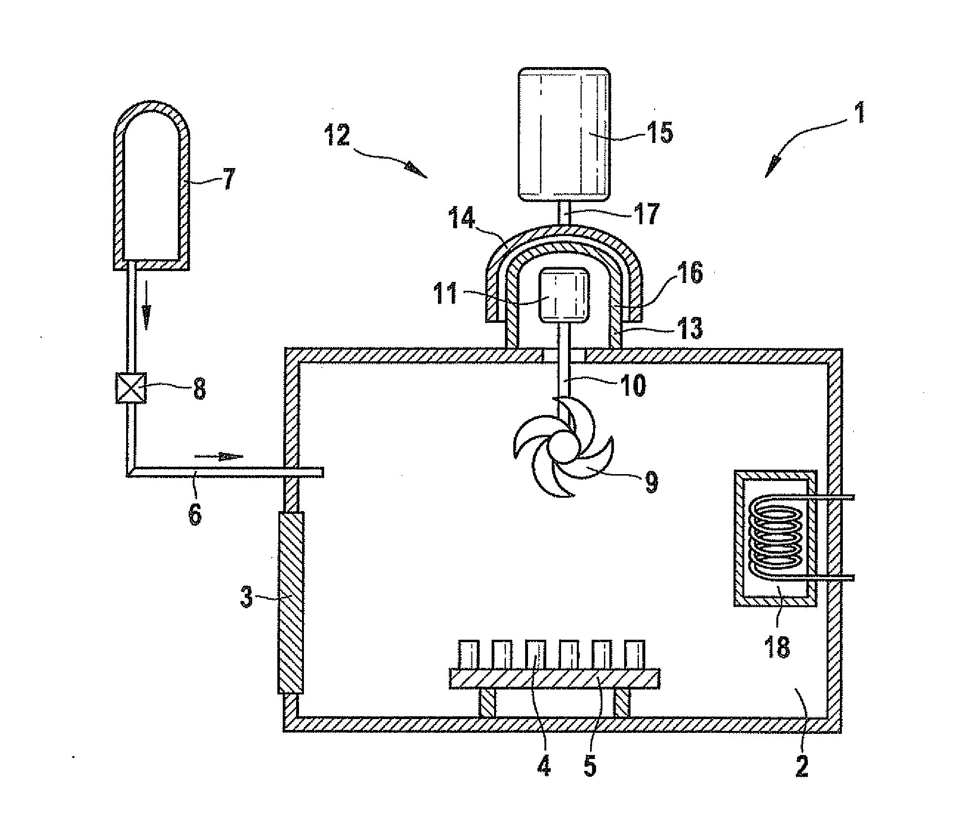
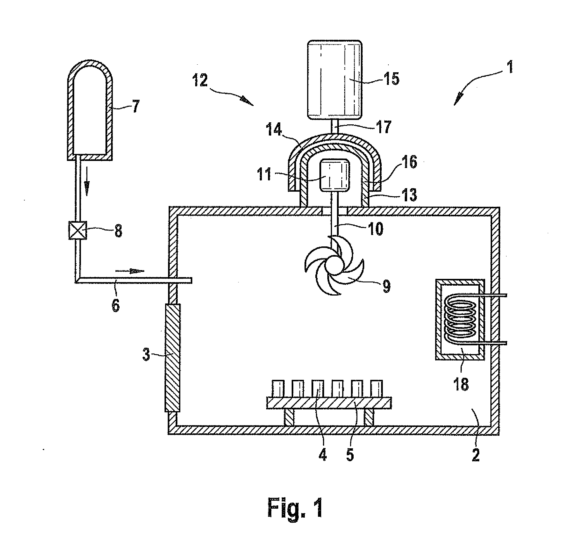
[0021]FIG. 1 shows a possible specific embodiment of a quenching device 1. In the depicted exemplary embodiment, quenching device 1 has a single chamber 2 that can be flooded with quenching gas. A floodable chamber in the form of a flow channel as shown in EP 1154 024 B1 does not exist here, but can be provided if needed.

[0022]Chamber 2 has a loading door 3 that can be sealed in pressure-tight fashion, through which chamber 2 (here the quenching chamber) can be loaded with material 4 that is to be quenched. For this purpose, material 4 that is to be quenched, which in the depicted exemplary embodiment is made up of steel workpieces, is placed on a charging rack 5 that, using suitable transport devices, can be transported into chamber 2 under a vacuum atmosphere and then transported out of said chamber after the quenching process.

[0023]An oven (not shown) for the preliminary heat treatment of quenching material 4 is standardly situated in front of loading door 3.

[0024]A quenching gas...


PUM

PropertyMeasurementUnit
Metallic bondaaaaaaaaaa
Magnetismaaaaaaaaaa
Torqueaaaaaaaaaa

Abstract

A quenching device is described that includes at least one chamber that can be filled with quenching gas and that has a blower wheel for circulating quenching gas, in particular a quenching chamber and / or a flow channel, a drive motor, situated outside the chamber, for driving the blower being allocated to the blower wheel. The drive motor is coupled to the blower wheel so as to transmit torque via a coupling that operates in contactless fashion. Also described is a related quenching method.

Description

FIELD OF THE INVENTION[0001]The present invention relates to a quenching device for quenching material that is to be quenched, in particular metallic workpieces, using quenching gas, as well as a quenching method for quenching material that is to be quenched, in particular metallic workpieces, using quenching gas.BACKGROUND INFORMATION[0002]In order to produce defined material properties, such as a high degree of hardness or sufficient resistance to wear, workpieces, usually made of metal, are subjected to thermal treatment. The most important factor in determining the result of this treatment is the speed with which the workpieces are cooled after having been heated. It is known to use water, oil, or quenching gas for the quenching process necessary for this purpose. The main advantage of using quenching gases instead of quenching liquids is that the material being quenched does not have to be cleaned after quenching, and that a higher degree of quenching homogeneity can be achieve...

Claims


Application Information

Patent Timeline
IPC IPC(8): C21D1/62C21D1/18
CPCC21D1/767C21D1/613
Inventor MUELLER, BERNHARDLOERCHER, MICHAEL
Owner ROBERT BOSCH GMBH
Why Eureka
Try Eureka