
Communication System and Method for Transmitting and Receiving Signals

a communication system and receiver technology, applied in the field of communication systems, can solve the problems of reducing the frequency of the impedance of the antenna is typically variable, etc., and achieves the effects of improving reducing the cost of the antenna, and increasing the efficiency of the communication system

Inactive Publication Date: 2012-03-15
QUALCOMM TECHNOLOGIES INC
View PDF6 Cites 12 Cited by
  • Summary
  • Abstract
  • Description
  • Claims
  • Application Information

AI Technical Summary

Benefits of technology

[0005]In one aspect, the invention improves the efficiency of the communication system. With higher efficiencies, smaller and cheaper antennas can be used.
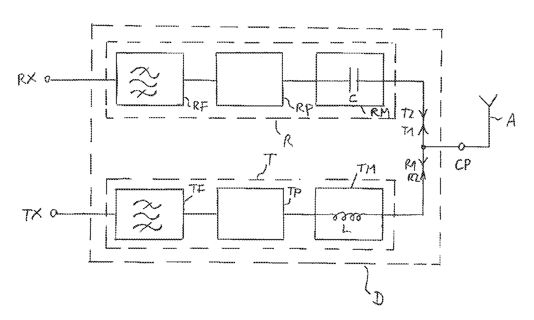
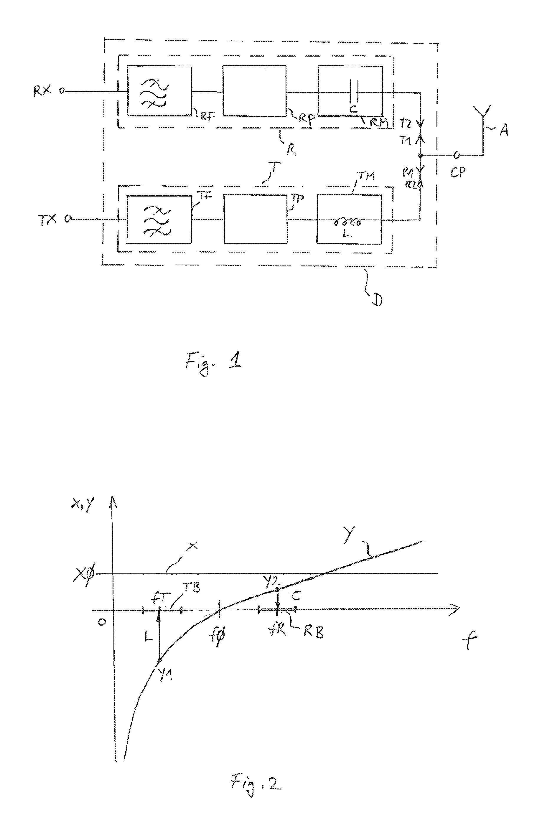
[0010]In an embodiment, the transmission matching network is a series inductor, wherein the reactance of the inductor cancels the reactance of the antenna at frequencies in the transmission band, and the reception matching network is a series capacitor, wherein the reactance of the capacitor cancels the reactance of the antenna at frequencies in the reception band. Alternatively, the transmission matching network is a series capacitor, wherein the reactance of the capacitor cancels the reactance of the antenna at frequencies in the transmission band, and the reception matching network is a series inductor, wherein the reactance of the inductor cancels the reactance of the antenna at frequencies in the reception band. The transmission branch and the reception branch can be matched independently of each other to the antenna for frequencies in the transmission band and in the reception band, respectively. Since the impedance matching only has to cover the frequencies in the transmission band or the reception band, a better matching can be achieved than when the impedance matching has to cover the frequencies in the transmission band and in the reception band as well as the frequencies lying between the transmission band and the reception band. A better matching of the transmission branch and the reception branch to the antenna reduces the insertion loss. Since the matching is only required for a much smaller bandwidth, antennas with higher quality factors Q can be used, enabling the use of smaller antennas.
[0011]In an embodiment, the transmission phase shifting network and the reception phase shifting network are transmission lines, wherein the transmission lines have phase shifts so that the transmission branch presents an open circuit for frequencies within the reception band, and the reception branch presents an open circuit for frequencies within the transmission band. The phase shifts are chosen such that incoming and reflected signals from the other frequency band cancel each other out within a branch. Each branch acts as an open circuit for the frequencies of the other branch, increasing the isolation between the branches.
[0012]In an embodiment, the transmission band and the reception band are separated in frequency from each other by more than twice the bandwidth of the transmission band for the bandwidth of the reception band. The invention is especially effective for increasing the efficiency of communication systems, where the transmission band and the reception band are separated by a larger range of frequencies, since no impedance matching for frequencies between the bands is required.
[0013]In an embodiment, the antenna has a quality factor greater than 20. Because of the separate matching of the transmission branch and the reception branch, antennas with higher quality factors Q can be used and matched to the duplexer. A high-quality factor Q allows smaller antennas to be used.
[0014]In an embodiment, the transmission filter passes frequencies within the transmission band and blocks frequencies within the reception band, the reception filter passes frequencies within the reception band and blocks frequencies within the transmission band, and at least one of the transmission filter and reception filter comprises a bulk acoustic wave (BAW) filter or a surface acoustic wave (SAW) filter. Both filters are band passes for frequencies in their own band and suppress frequencies from the other band in order to increase the isolation between the transmission branch and the reception branch. Bulk acoustic wave filters have low insertion losses within the pass band and have a high rejection outside the pass band.

Problems solved by technology

However, the impedance of the antenna typically varies considerably over frequency.
As a result, the transmission branch and the reception branch are usually poorly matched to the antenna which reduces the efficiency of the communication system.

Method used


Image

  • Communication System and Method for Transmitting and Receiving Signals
  • Communication System and Method for Transmitting and Receiving Signals

Examples


Embodiment Construction

[0053]FIG. 1 shows a block diagram of an embodiment of the communication system. The communication system comprises a duplexer D having a reception port RX, a transmission port TX and a common port CP. An antenna A is coupled to the common port CP. The duplexer D allows full-duplex operation: signals having frequencies in a transmission band TB can be applied to the transmission port TX and transmitted by the antenna A while at the same time signals having frequencies in a reception band RB can be received by the antenna A and can be tapped off at the reception port RX. The same antenna A is used for simultaneously receiving and transmitting signals at different frequencies.

[0054]The duplexer D comprises a transmission branch T and a reception branch R. The transmission branch T and the reception branch R are connected by the transmission port TX and the reception port RX, respectively, and are coupled to one another and to the antenna A at the common port CP. The transmission branc...


PUM


Abstract

A communication system transmits signals having frequencies that lie within a transmission band and receives signals having frequencies that lie within a reception band. The system includes a duplexer and an antenna. The duplexer includes a transmission branch and a reception branch. The transmission branch includes a transmission filter, a transmission phase shifting network and a transmission matching network. The reception branch includes a reception filter, a reception phase shifting network and a reception matching network. The transmission matching network and the reception matching network have predominately constant phase shifts over frequencies within the reception band and within the transmission band, respectively. The antenna is coupled to the transmission matching network and to the reception matching network, and shows a predominantly reactance-only impedance variation over frequencies in the transmission band and over frequencies in the reception band.

Description

[0001]This patent application is a national phase filing under section 371 of PCT / EP2010 / 052560, filed Mar. 1, 2010, which claims the priority of European patent application 09154231.6, filed Mar. 3, 2009, each of which is incorporated herein by reference in its entirety.BACKGROUND[0002]The invention concerns a communication system for transmitting signals having frequencies that lie within a transmission band and for receiving signals having frequencies that lie within a reception band. Such communication systems are used, for example, in mobile phones operating in full-duplex mode, where signals are transmitted and received simultaneously in two different frequency bands. These communication systems usually comprise a duplexer having a transmission branch and a reception branch, where both the transmission branch and the reception branch are connected to a common antenna.[0003]The transmission branch and the reception branch need to be isolated from one another so that transmissio...

Claims


Application Information

Patent Timeline
IPC IPC(8): H04B7/00H01Q1/50H03H7/46
CPCH04B1/52H04B1/18
Inventor BOYLE, KEVIN R.
Owner QUALCOMM TECHNOLOGIES INC
Learn More