
Light module

Active Publication Date: 2012-03-15
KONINKLIJKE PHILIPS ELECTRONICS NV
View PDF2 Cites 0 Cited by
  • Summary
  • Abstract
  • Description
  • Claims
  • Application Information

AI Technical Summary

Benefits of technology

[0007]It would be desirable to provide an improved light module which is protected from overheating. It would also be desirable to provide an improved light module which gives immediate feedback to a user about the sufficiency of the thermal attachment.
[0008]To better address one or more of these concerns, in a first aspect of the invention a light module for electrical and thermal attachment to an energy infrastructure having at least one power supply, each power supply comprising two electrodes, said light module comprising a light source to emit light, wherein the light source is a heat source when emitting light, two electrical contacts to contact the electrodes of the at least one power supply and thereby establishing the electrical attachment between the light module and the energy infrastructure, a control system arranged between the light source and the electrical contacts to control a power supplied to the light source, wherein the light module comprises a measurement system to measure a thermal resistance of the thermal attachment between the light module and the energy infrastructure when establishing the electrical attachment, and wherein the control system is configured to reduce the power supplied to the light source when the thermal resistance is above a predetermined value to protect the light module from overheating.
[0012]reducing a power supplied to the light source by a control system when the thermal resistance is above a predetermined value to protect the light module from overheating.
[0013]Further, in combination a light module for electrical and thermal attachment to an energy infrastructure and the energy infrastructure is provided, said energy infrastructure having at least one power supply, each power supply comprising two electrodes, and said light module comprising a light source to emit light, wherein the light source is a heat source when emitting light, two electrical contacts to contact the electrodes of the at least one power supply and thereby establishing the electrical attachment between the light module and the energy infrastructure, a control system arranged between the light source and the electrical contacts to control a power supplied to the light source, wherein the light module comprises a measurement system to measure a thermal resistance of the thermal attachment between the light module and the energy infrastructure when establishing the electrical attachment, and wherein the control system is configured to reduce the power supplied to the light source when the thermal resistance is above a predetermined value to protect the light module from overheating.

Problems solved by technology

A drawback of the current light modules is that when a user positions or repositions the light module, there is a risk of insufficient thermal contact resulting in a relatively high thermal resistance of the thermal attachment.
The light module will then overheat, which reduces the light output and may even cause permanent damage to the light module.
However, a drawback of these solutions is that when overheating is measured, the light module already has some so-called burning time at an elevated temperature, which still may cause damage to the light module.
Another drawback may be that the user does not get immediate feedback that the thermal contact between light module and energy infrastructure is insufficient.

Method used


Image

  • Light module
  • Light module
  • Light module

Examples


Embodiment Construction

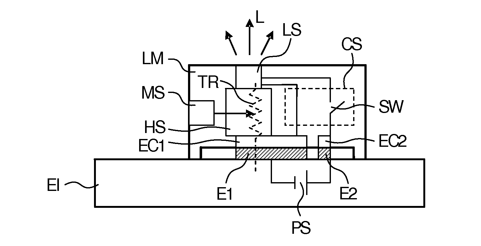
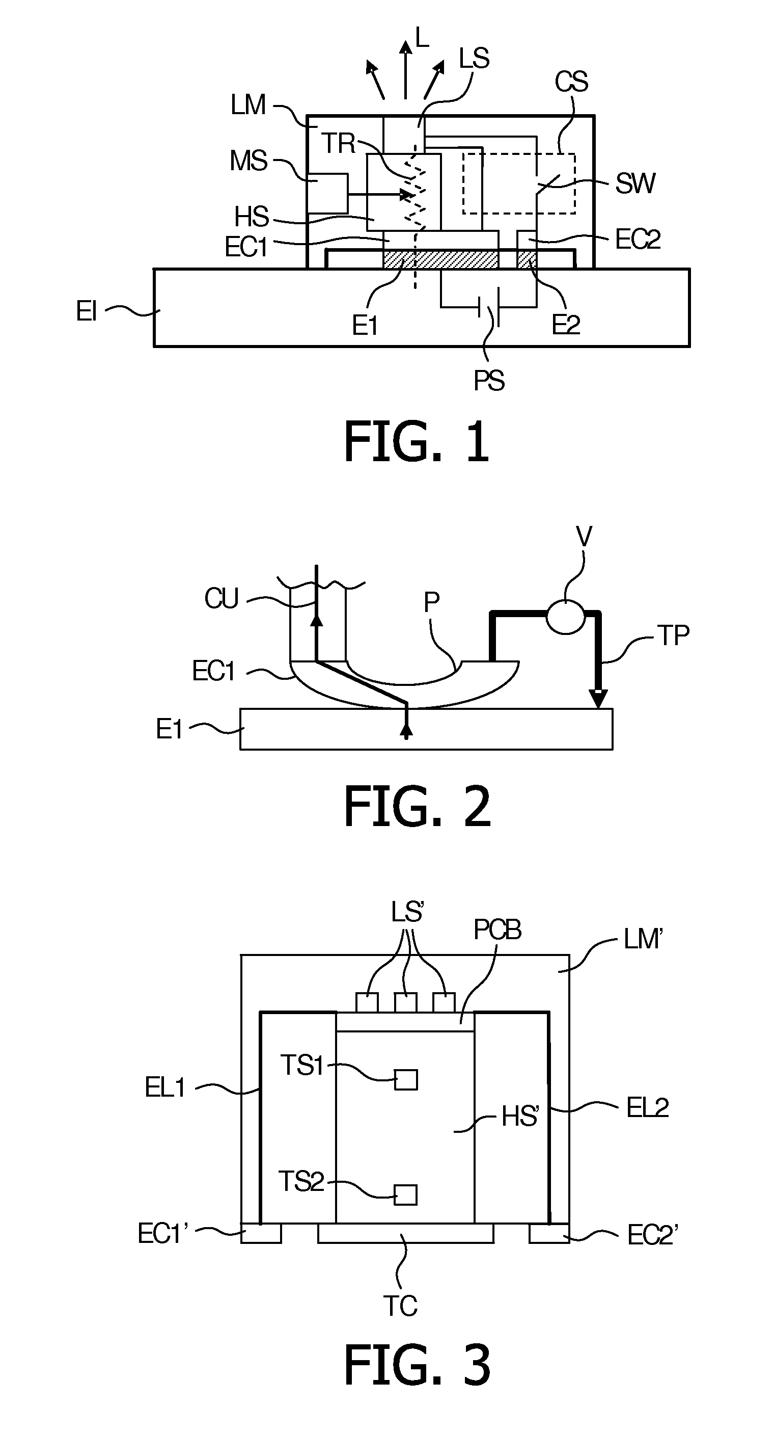
[0020]FIG. 1 depicts a light module LM for electrical and thermal attachment to an energy infrastructure EI having at least one power supply PS, wherein each power supply comprises two electrodes E1, E2. The light module LM comprises a light source LS to emit light L which is a heat source when emitting light L, two electrical contacts EC1, EC2 to contact the electrodes E1, E2 of the at least one power supply PS and thereby establishing the electrical attachment between the light module LM and the energy infrastructure EI, a control system CS arranged between the light source LS and the electrical contacts EC1, EC2 to control a power supplied to the light source LS, and a measurement system MS to measure a thermal resistance TR of the thermal attachment between the light module LM and the energy infrastructure EI when establishing the electrical attachment. The control system CS is configured to reduce the power supplied to the light source LS when the thermal resistance TR is above...


PUM


Abstract

The invention relates to a light module for electrical and thermal attachment to an energy infrastructure having at least one power supply, each power supply comprising two electrodes, said light module comprising a light source to emit light, wherein the light source is a heat source when emitting light, two electrical contacts to contact the electrodes of the at least one power supply and thereby establishing the electrical attachment between the light module and the energy infrastructure, a control system arranged between the light source and the electrical contacts to control a power supplied to the light source, wherein the light module comprises a measurement system to measure a thermal resistance of the thermal attachment between the light module and the energy infrastructure when establishing the electrical attachment, and wherein the control system is configured to reduce the power supplied to the light source when the thermal resistance is above a predetermined value to protect the light module from overheating. The invention also relates to a method for protecting a light module from overheating.

Description

FIELD OF THE INVENTION[0001]The invention relates to the field of light modules, and more specifically to light modules for electrical and thermal attachment to an energy infrastructure.BACKGROUND OF THE INVENTION[0002]A light module comprises a light source to emit light and is preferably easily attachable to an energy infrastructure having at least one power supply, wherein each power supply comprises two electrodes. The energy infrastructure may take the form of the well known halogen wire systems or a 2D electrode configuration.[0003]Preferably, the attachment of the light module to the energy infrastructure is made by hand without using any additional tools, for example by clamping and / or magnetic sticking. This allows a user without technical knowledge to attach the light module to the energy infrastructure. However, screwing or bolting is also possible.[0004]The light source is usually also a heat source when emitting light, and in order to keep the light module small, it is ...

Claims


Application Information

Patent Timeline
IPC IPC(8): H05B37/02H05B44/00
CPCH05B33/0872Y02B20/341H05B33/089Y02B20/30H05B45/56H05B45/20H05B45/24
Inventor LENDERINK, EGBERTWILLEMSEN, OSCAR HENDRIKUSCALON, GEORGES MARIE
Owner KONINKLIJKE PHILIPS ELECTRONICS NV
Learn More