
Refrigerator energy and temperature control

a technology of refrigerator and energy, applied in the field of refrigerator, can solve the problems of increased difficulty in internal humidity control, increased start loss and reliability penalties, etc., and achieve the effect of improving cycle efficiency

Active Publication Date: 2012-03-15
HAIER US APPLIANCE SOLUTIONS INC
View PDF12 Cites 43 Cited by
  • Summary
  • Abstract
  • Description
  • Claims
  • Application Information

AI Technical Summary

Benefits of technology

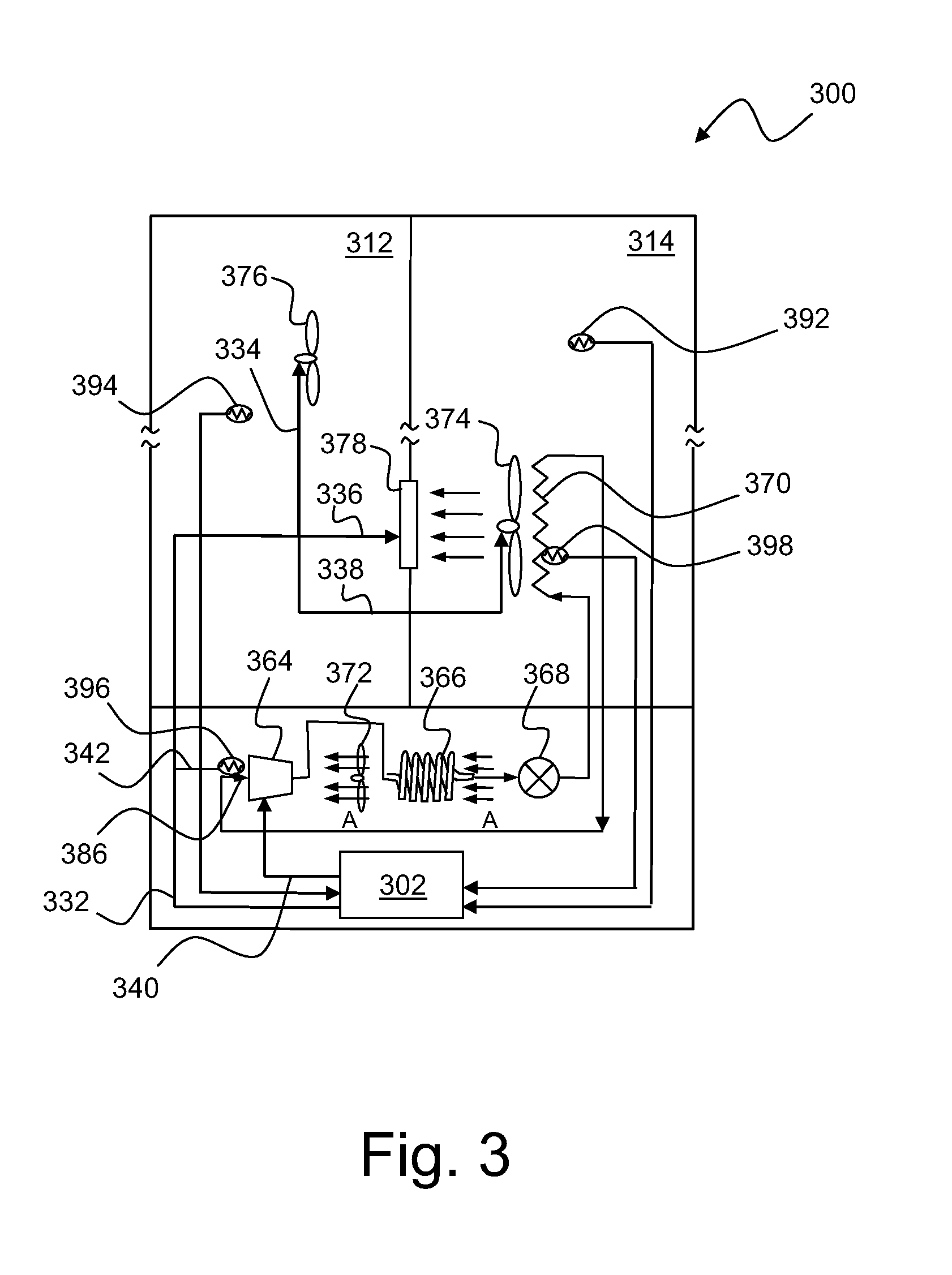
The present invention relates to a refrigerator with improved cycle efficiency and temperature control. The invention includes a controller that continuously modulates the speed of various components such as the evaporator fan, condenser fan, and fresh food fan to maintain prescribed compartment conditions based on feedback from sensors and thermodynamic interactions between the refrigerator components. The invention also includes a housing with multiple temperature sensors and a damper between the fresh food compartment and the freezer compartment. The controller can be configured as a proportional, proportional-integral, or proportional-integral-derivative controller to achieve the desired temperature control. Overall, the invention provides efficient refrigeration and precise temperature control for the refrigerator.

Problems solved by technology

Such systems include certain inherent inefficiencies such as having to run at lower than optimal evaporation temperatures in order to allow the unit to cycle off for a reasonable amount of time, as well as start losses and reliability penalties associated with starting and stopping a sealed system.
In addition, internal humidity control is made more difficult due to off cycle time.

Method used


Image

  • Refrigerator energy and temperature control
  • Refrigerator energy and temperature control
  • Refrigerator energy and temperature control

Examples


Embodiment Construction

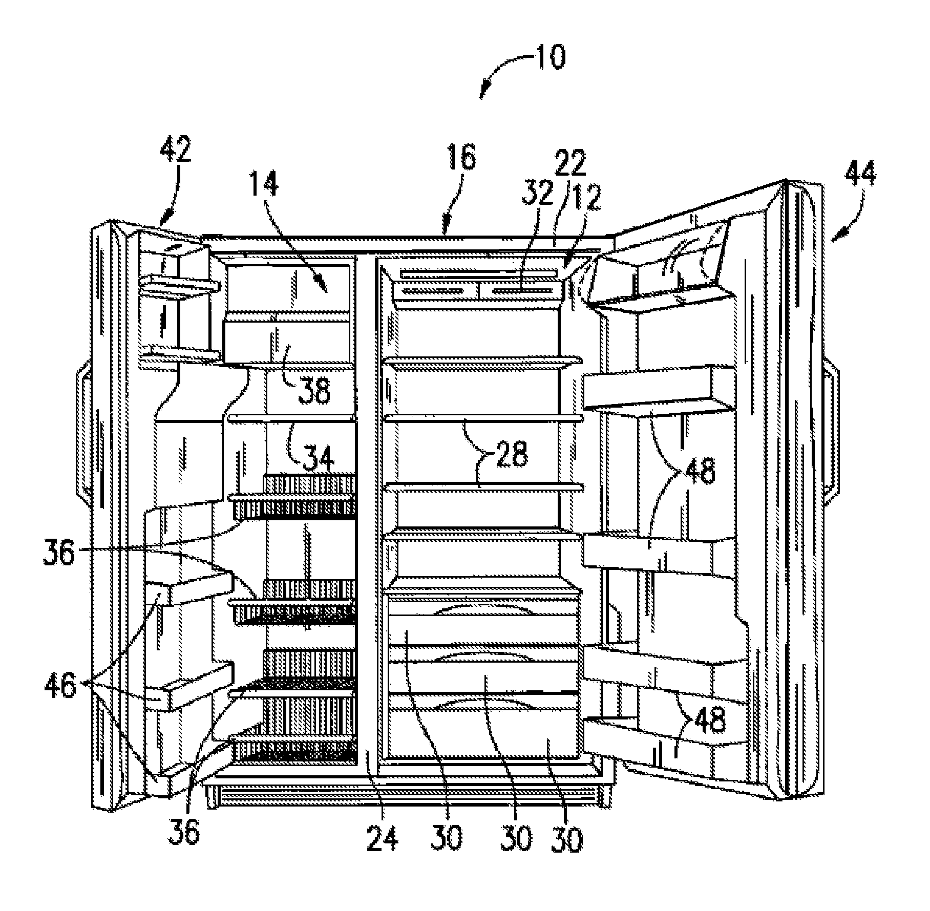
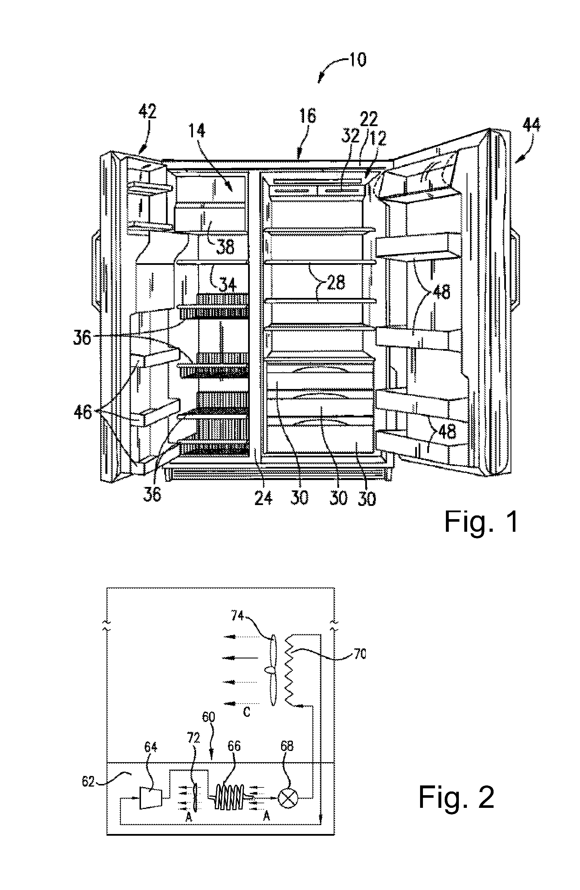
[0019]Reference now will be made in detail to embodiments of the invention, one or more examples of which are illustrated in the drawings. Each example is provided by way of explanation of the invention, not limitation of the invention. In fact, it will be apparent to those skilled in the art that various modifications and variations can be made in the present invention without departing from the scope or spirit of the invention. For instance, features illustrated or described as part of one embodiment can be used with another embodiment to yield a still further embodiment. Thus, it is intended that the present invention covers such modifications and variations as come within the scope of the appended claims and their equivalents.

[0020]As noted in the Summary section, the present subject matter is directed toward methods of improved energy consumption through precise temperature control for a refrigerator applying the fundamentals of proportional-integral-differential (PID) feedback...


PUM


Abstract

Apparatus and methodologies are provided to improve the refrigeration system by precisely controlling refrigerator compartment and heat exchanger temperatures through continuous modulation of device speeds or positions to match capacity with instantaneous load. A controller in a refrigerator is configured to provide a plurality of control loops to control various operational aspects of selected components in the refrigerator. A first loop controls the operating speed of a compressor based on temperature of the evaporator or based on the desired speed of an evaporator fan. A second control loop controls speed of an evaporator fan to maintain a prescribed freezer compartment temperature. A third control loop maintains a prescribed temperature in a fresh food compartment. In certain embodiments selected of the control loops may be thermodynamically coupled by way of thermal interaction between the various cooled compartments rather than being electrically coupled. The control loops may be individually configured as one of a proportional, proportional-integral, or proportional-integral-derivative control loop.

Description

FIELD OF THE INVENTION[0001]The present subject matter relates to refrigerators. More particularly, the present subject matter relates to improved energy consumption and temperature control within refrigerator compartments.BACKGROUND OF THE INVENTION[0002]Currently available refrigeration systems employ banded temperature control schemes that operated as either ON / OFF or LOW, MED, HIGH and required operational deadbands within their temperature control systems. Such systems include certain inherent inefficiencies such as having to run at lower than optimal evaporation temperatures in order to allow the unit to cycle off for a reasonable amount of time, as well as start losses and reliability penalties associated with starting and stopping a sealed system. In addition, internal humidity control is made more difficult due to off cycle time.[0003]In view of these concerns, it would be'advantageous to provide a refrigeration system that could provide a continuously modulated compressor,...

Claims


Application Information

Patent Timeline
Patent Type & Authority Applications(United States)
IPC IPC(8): F25B1/00
CPCF25B2600/0253F25B2600/111F25B2600/112F25D17/045Y02B30/743F25D2700/12F25D2700/122Y02B30/741F25D29/00Y02B30/70
Inventor MAY, JASON ANDREWSCHORK, BRIAN MICHAELBECKLEY, BRYAN JAMES
Owner HAIER US APPLIANCE SOLUTIONS INC
Learn More