
Network-enabled valve management system

a management system and network-enabled technology, applied in the direction of emergency/hazardous communication services, instruments, electrical equipment, etc., can solve the problems of vehicle cost, labor cost (including fuel and maintenance cost, time required, etc.) and number of costs associated

Inactive Publication Date: 2012-03-08
QMI MFG
View PDF13 Cites 51 Cited by
  • Summary
  • Abstract
  • Description
  • Claims
  • Application Information

AI Technical Summary

Benefits of technology

"The present invention aims to provide a system for remotely operating endpoint devices, such as valves and sensors, in response to emergency situations, such as gas leaks or power failures. The system includes a server, network access hubs, and endpoint devices. The network access hubs can detect and respond to earthquakes, and the endpoint devices can control valves and other devices to manage utility services. The system can also include a light source for street lighting and a sensor for detecting gas leaks. The technical effects of the invention include the ability to remotely control endpoint devices and detect and respond to emergency situations."

Problems solved by technology

There are a number of costs associated with this approach, including labour cost (including time required for travel and for completing the job) and vehicle cost (including fuel and maintenance cost).

Method used


Image

  • Network-enabled valve management system
  • Network-enabled valve management system
  • Network-enabled valve management system

Examples


Embodiment Construction

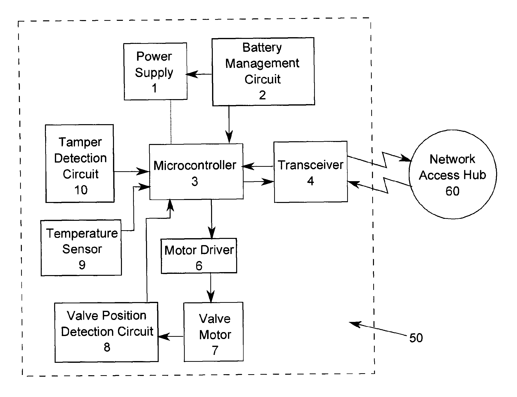
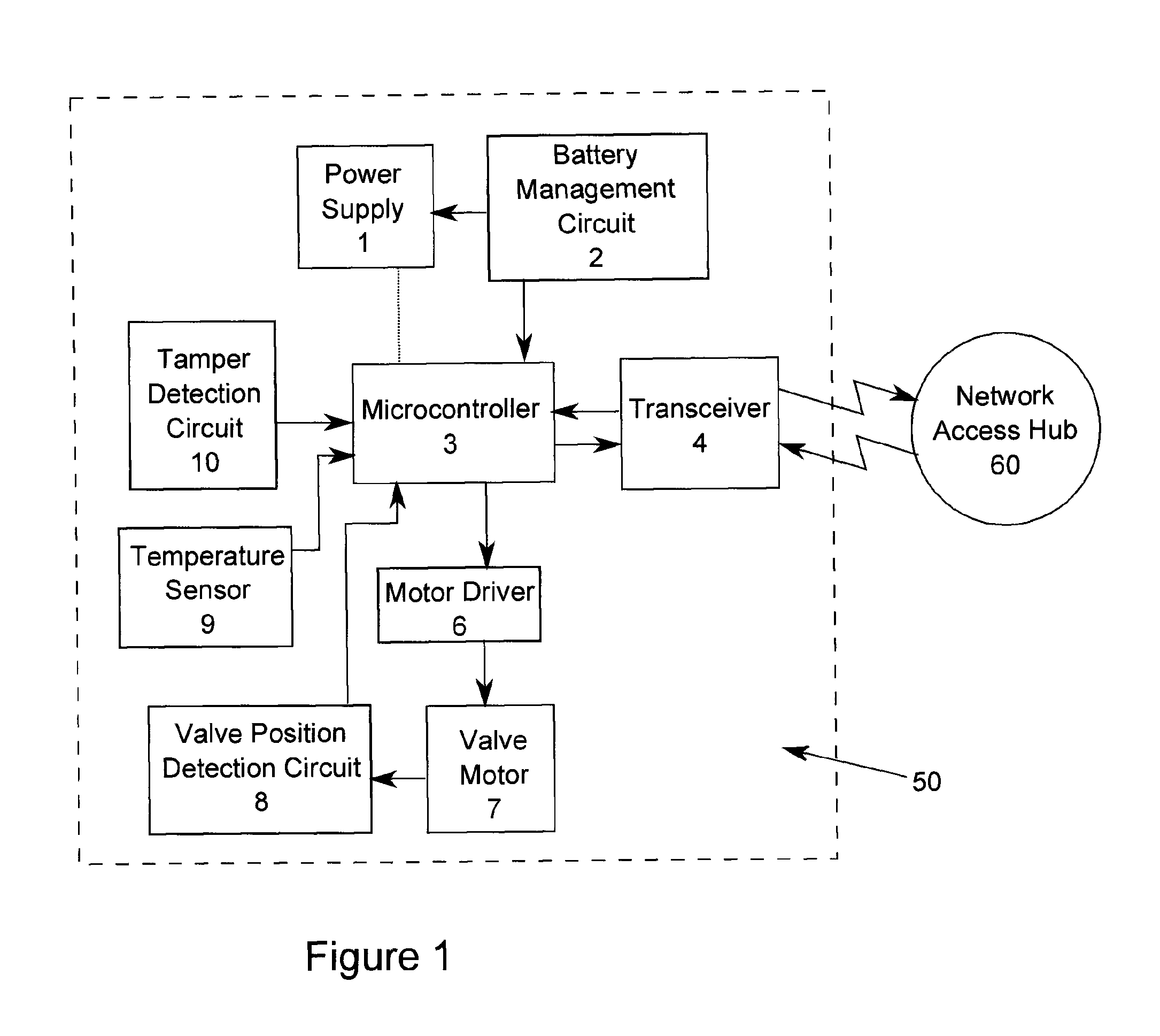
[0017]Referring to FIGS. 1 and 2, the present invention comprises one or more endpoint devices 50 and one or more network access hubs 60. Referring in particular to FIG. 1, the endpoint device 50 is preferably a valve for controlling gas, oil, water, or some other utility service. In the preferred embodiment, the endpoint device 50 is an electrically operated, battery-powered valve, although the valve may also be pneumatically actuated instead. The valve is preferably a quarter-turn ball valve or a butterfly valve with a position sensor consisting of limit switches and rotary encoder for accurate position determination. In the case where the endpoint device 50 is a valve, it comprises a transceiver 4, a motor driver 6, a valve motor 7, a microcontroller 3, and a power supply 1.

[0018]The transceiver 4 is preferably a two-way radio that provides a secure two-way wireless radio link between the endpoint device 50 and the network access hub 60. Preferably, this link is encrypted to prev...


PUM


Abstract

A system for remotely operating endpoint devices, such as valves for utility services, comprises a server, one or more network access hubs, and one or more endpoint devices. The network access hubs communicate with the server through a network and communicate wirelessly with the endpoint devices. The network access hubs transmit instructions to the endpoint devices to control the operation of the endpoint devices. The network access hubs may also comprise earthquake detection circuits to detect possible earthquakes and transmit instructions to the endpoint devices to close valves accordingly.

Description

FIELD OF THE INVENTION[0001]The present invention relates to automatic control of valves. In particular, the present invention relates to automatic control of valves for gas, oil, water or other fluids.BACKGROUND OF THE INVENTION[0002]Valves are typically used to control utility service (such as gas or water) to customers. For example, quarter-turn valves are commonly used for gas and water connections. Such valves are usually operated manually, with a technician turning a handle to control the flow of the utility service.[0003]Traditionally, to stop or restore gas, water, or other utility service to a customer, a utility company would send a technician to the location to manually unlock and open, or close and lock a valve. There are a number of costs associated with this approach, including labour cost (including time required for travel and for completing the job) and vehicle cost (including fuel and maintenance cost).SUMMARY OF THE INVENTION[0004]The objectives of the present inv...

Claims


Application Information

Patent Timeline
Patent Type & Authority Applications(United States)
IPC IPC(8): G05B23/02
CPCG05B9/02H04W76/007H04W4/22H04W76/50H04W4/90
Inventor HANRAHAN, MICHAELWOOD, RAYMOND
Owner QMI MFG
Learn More