
Cleaning method and system

a cleaning method and system technology, applied in the direction of cleaning using liquids, filtration separation, separation processes, etc., can solve the problems of reducing filtration efficiency, clogging pores, affecting the cleaning effect, etc., and achieve the effect of effective cleaning

Inactive Publication Date: 2012-03-08
FUJIFILM PLANAR SOLUTIONS
View PDF7 Cites 8 Cited by
  • Summary
  • Abstract
  • Description
  • Claims
  • Application Information

AI Technical Summary

Benefits of technology

[0017]This disclosure relates to a cleaning method for a particle contaminated surface, e.g., porous surfaces, media for cartridge, pleated and membrane surfaces, and internal walls of tanks or filter housings. Cleaning compositions, e.g., chemical solutions and mixtures, are used to partially or completely dissolve the particles without causing any damage to the particle contaminated surface. This allows effective cleaning and reuse of the contaminated media, e.g., filters.

Problems solved by technology

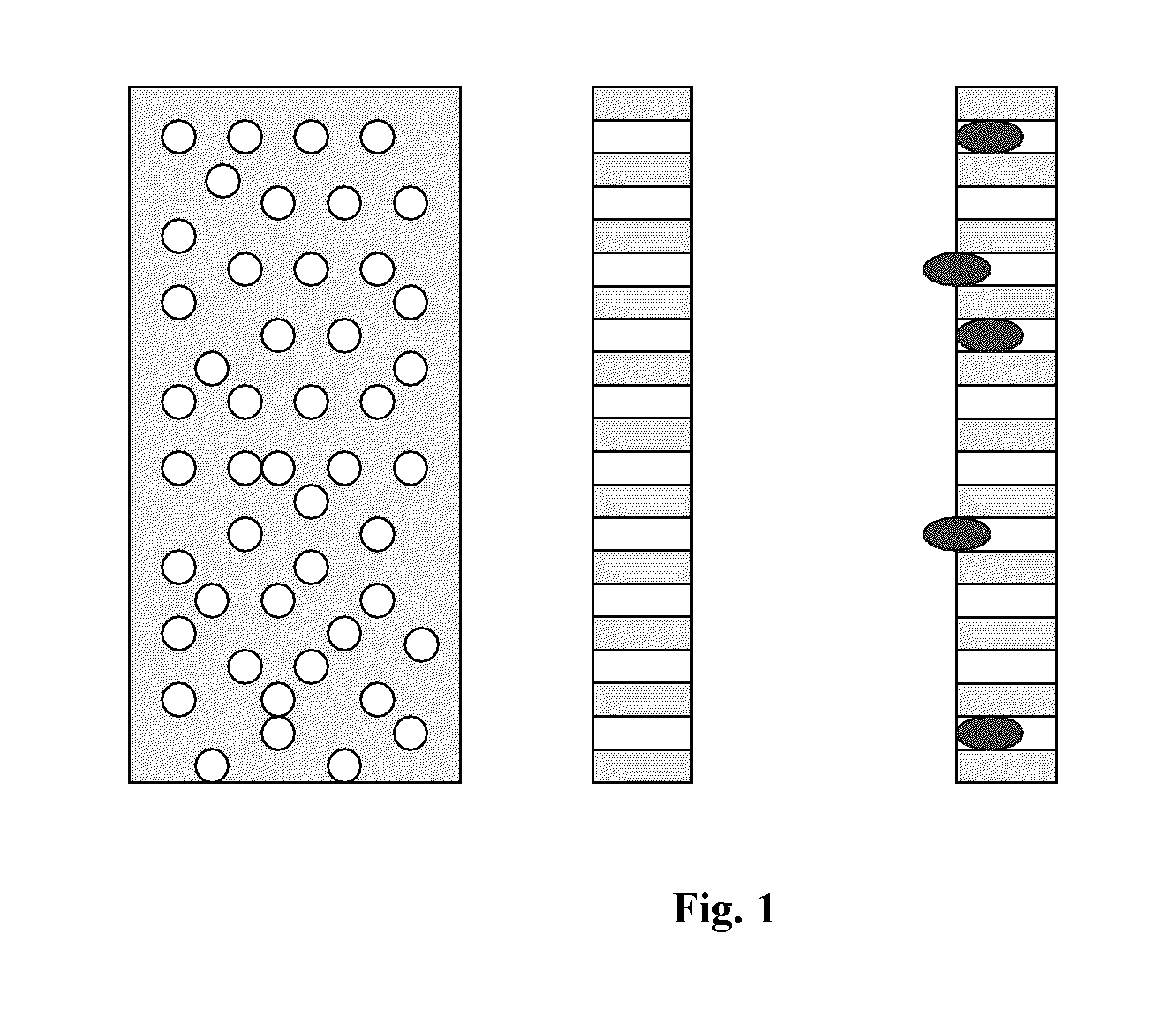
Constant contact of these colloidal dispersions with the porous media results in contamination of the surface and clogging of the pores.
Eventually these particles fill up the pore and clog it, reducing filtration efficiency and increasing the differential pressure needed to force the colloidal dispersions through the media.
Many reactors or storage tanks will eventually develop particle contaminated porous surfaces which are stubborn films or deposits of solidified particles.
Tanks and filter housings are complicated enclosures and are not easily accessible.
Power washing big tanks or housings requires intricate equipment and, many times, hard to reach places or “dead” locations are not properly cleaned.
Because of this issue, tanks are not fully cleaned.
These attempts did not result in full recovery.
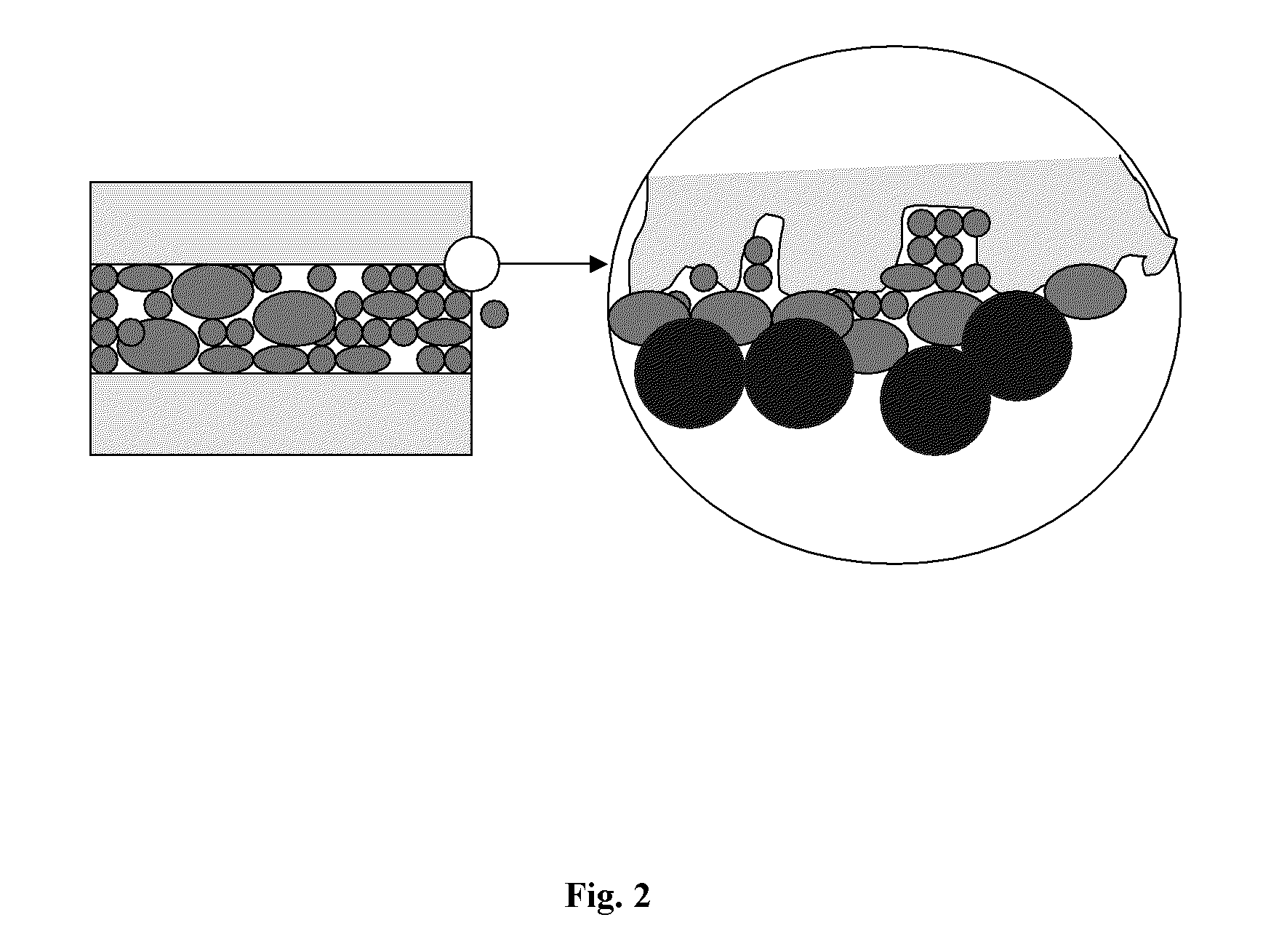
A major reason for this failure is that very small particles that get trapped inside the filter pores form strong mechanical and sometimes chemical bonds with the filter surfaces.
Mechanical removal of the particles from these rough areas can be very difficult.
Larger particles in these slurries are undesirable since they can create defects on wafer surfaces.
This advanced filtration is an expensive process.
Filter replacement can take a long time, thereby increasing the process cycle time.
The clogged particles adhere strongly to the pores and filter surfaces and cannot simply be forced loose with high pressure water.

Method used


Image

  • Cleaning method and system
  • Cleaning method and system
  • Cleaning method and system

Examples


example 1

[0104]A fumed silica dispersion was circulated through three filter housings with filter pores ranging between 0.1-1 microns in size. These tight pores are considered more challenging to be reconditioned in contrast to pores higher than one micron size. Once the filters plugged, pressurized water was circulated through the filters. The fumed silica dispersions were re-filtered. However the differential pressure had not come down, indicating that the pores were still clogged.

example 2

[0105]Through the same filters described in Example 1, a heated (50° C.) KOH aqueous solution was circulated for 10 minutes. Water rinse followed to rinse off KOH and decrease the pH. Only then, filters were reconditioned and ready for re use. Fumed dispersions were then filtered through the same filters. The LPC (Large Particle Counts), MPS (Mean Particle Size), % TS (Total Solids) data of fumed silica show complete cleaning and recovery of filtration efficiency.

example 3

[0106]The process in Example 2 was repeated on the same filters for several times. Every time the cleaning resulted in complete recovery of filtration efficiency.


PUM

PropertyMeasurementUnit
Temperatureaaaaaaaaaa
Compositionaaaaaaaaaa
Dynamicaaaaaaaaaa

Abstract

A method for removing particles or deposits from a surface having particles or deposits thereon. The method involves contacting a surface with a chemical composition sufficient to selectively dissolve and remove at least a portion of the particles or deposits from the surface. The chemical composition is compatible with the surface. This disclosure also relates to a system of specially designed equipment for removing particles or deposits from a surface having particles or deposits thereon. The disclosure is useful, for example, in cleaning porous surfaces, media for cartridge, pleated and membrane surfaces, and internal walls of tanks or filter housings.

Description

[0001]This application claims the benefit of provisional U.S. Application Ser. No. 61 / 379,577, filed Sep. 2, 2010, the entirety of which is incorporated herein by reference.BACKGROUND[0002]1. Field of the Disclosure[0003]This disclosure generally relates to a method for removing particles or deposits from a surface having particles or deposits thereon. Chemical compositions, e.g., chemical solutions and mixtures, are used to partially or completely dissolve the particles or deposits, and are compatible with the surface. This disclosure also relates to a system of specially designed equipment for removing particles or deposits from a surface having particles or deposits thereon. The disclosure is useful, for example, in cleaning porous surfaces, media for cartridge, pleated and membrane surfaces, and internal walls of tanks or filter housings.[0004]2. Discussion of the Background Art[0005]In a number of industrial applications, porous surfaces and media are used where they come in co...

Claims


Application Information

Patent Timeline
IPC IPC(8): B01D29/00B08B3/12B08B3/00C09K13/00C11D17/00C09K13/04C09K13/02B08B7/04B08B9/00
CPCC09K13/00C11D3/43B08B3/14B08B3/08C11D7/50B01D41/04B01D29/62B01D41/00
Inventor MOHSENI, SAEED H.MAHULIKAR, DEEPAKGRAMM, ELIZABETH
Owner FUJIFILM PLANAR SOLUTIONS
Learn More