
Feeding method and feeding system for farmed fish

a technology for farmed fish and supply methods, applied in pisciculture, climate change adaptation, applications, etc., can solve the problems of reducing profitability, underfeeding not only reduces profitability, and slowing fish growth

Inactive Publication Date: 2012-03-08
NIPPON SUISAN KAISHA LTD
View PDF13 Cites 11 Cited by
  • Summary
  • Abstract
  • Description
  • Claims
  • Application Information

AI Technical Summary

Benefits of technology

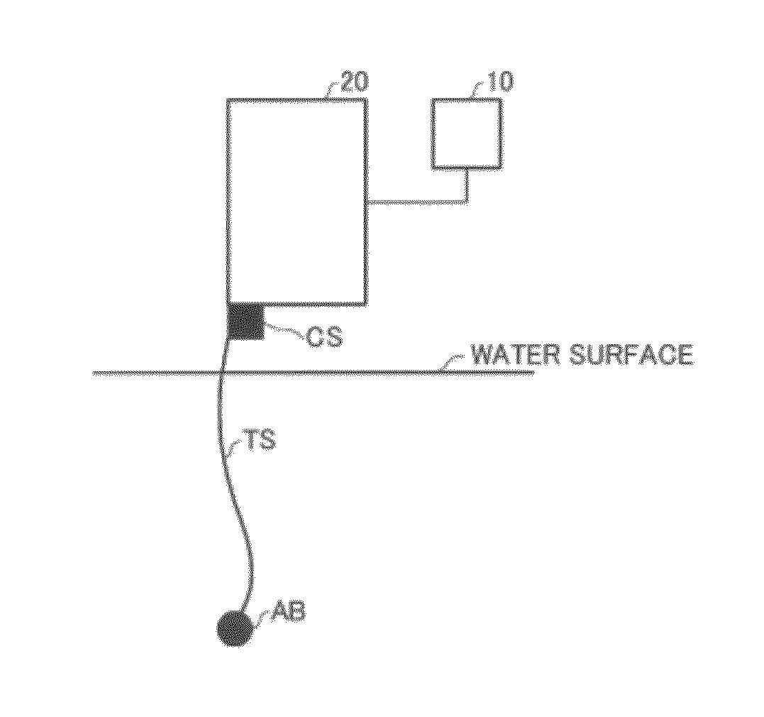
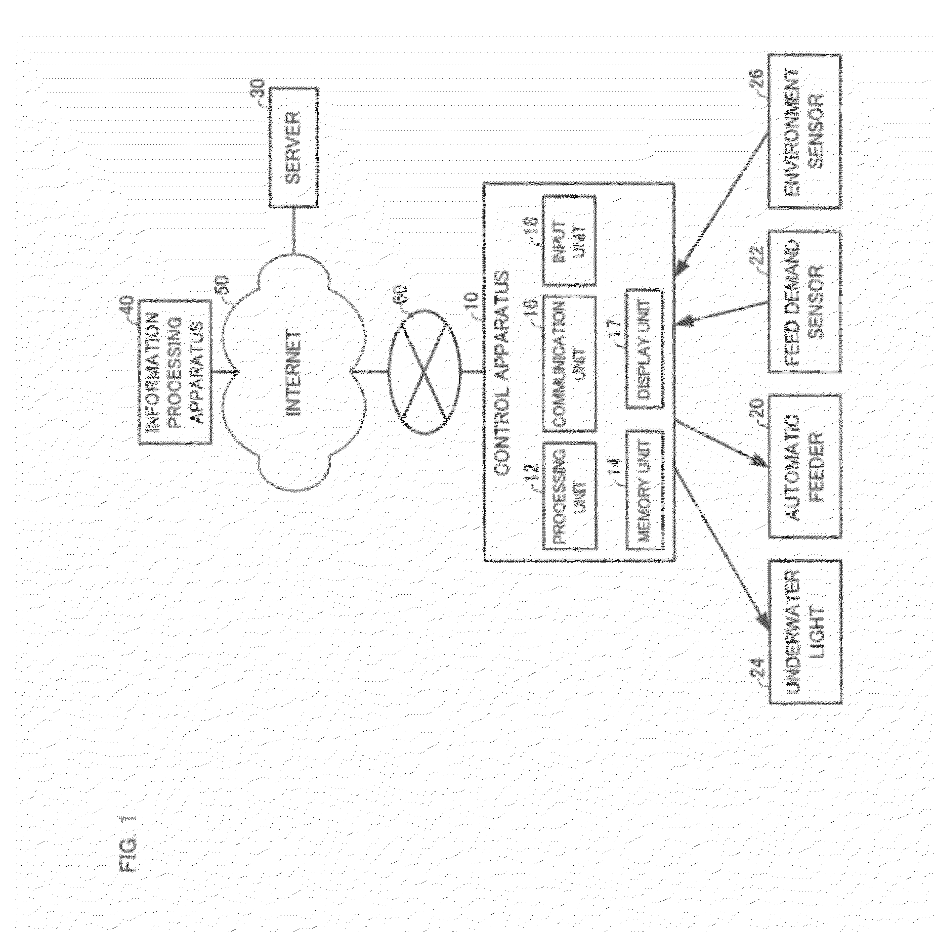
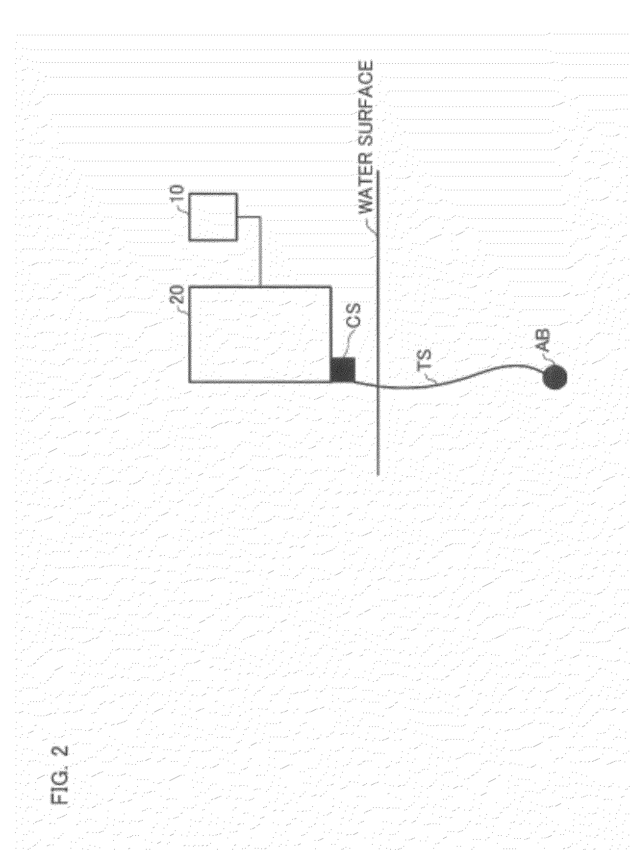
[0018]The present invention does not simply combine automatic feeding and self-activated feeding, but uses information from a feed demand sensor, which is used for the self-activated feeding, to adjust the feeding schedule of the automatic feeding. According to the present invention, feed supplied from the automatic feeder is adjusted based on detection results from a feed demand sensor that detects feed demand from the farmed fish, thereby allowing an appropriate quantity of feed to be supplied in response to changes in the appetite of the fish while preserving the advantages of supplying feed using the automatic feeder.

Problems solved by technology

While such methods do allow savings to be made the labor associated with feeding work, risk of underfeeding and overfeeding is high due to the difficulty of responding to changes in the appetite of the fish.
Overfeeding not only reduces profitability, but is also a cause of pollution of the sea at the site of the farm.
On the other hand, underfeeding slows the growth of the fish.
However, in the self-activated type feeding systems, the self-activation behavior of the fish ceases before they are full, and these methods therefore carry the risk that the fish will not grow sufficiently (see “Youshoku” (Fish Farming) February 2009 issue, pp 5 to 8).
Also, when self-activated feeding demand method is used on groups of fish, it has been reported that only a specific limited number of the individual fish behave in a way that demands feeding (Physiology and Behavior 2002, Issue 76, pp 281 to 287), and there is therefore a risk that variations in the amount of feeding will occur within the group, resulting in a loss of feeding efficiency.

Method used


Image

  • Feeding method and feeding system for farmed fish
  • Feeding method and feeding system for farmed fish
  • Feeding method and feeding system for farmed fish

Examples


working example

3. WORKING EXAMPLE

Test Results

3-1. Working Example 1

[0079]FIG. 6 shows test results (working example 1) for the feeding system of the present embodiment.

[0080]Here, a total of 3 cages were prepared, including a cage for performing only automatic feeding in accordance with the feeding schedule (automatic feeding test section), a cage for performing only self-activated feeding using the feed demand sensor (self-activated feeding test section) and a cage for combining automatic feeding and self-activated feeding according to the method of the present embodiment (combined test section), 200 yellowtail were housed in each cage, and a test was performed for two months.

[0081]In the automatic feeding test section, feed was supplied in 200 g lots, a predetermined number of times (initially 60 times and subsequently 30 times) at 2 minute intervals every evening (initially 17:00 and subsequently 16:30), and adjusted so that that the daily feeding rate was 1.3% to 0.6% of the overall weight of ...

working example 2

3-2. Working Example 2

[0085]FIG. 7 shows results from Working Example 2.

[0086]Here, two cages were prepared, including a cage for which hand feeding by a trained person (hand feeding section) was performed and a cage for which automatic feeding and self-activated feeding were combined according to the method of the present embodiment (combined test section). The cages of 10 m×10 m, the size of cages used in actual fish farming, housed 11908 fish and 12599 yellowtail respectively, and a test was performed for two months during a period of low water temperature. The hand feeding by a trained person is performed by finely adjusting the quantity of feed while observing the state of feeding at the water surface. Hence, the average increase in body weight was expected to be larger, and the feed conversion ratio and degree of variation was expected to be smaller than in the regular automatic feeding test section and self-activated feeding test section. In reality, in many fish farms where ...

working example 3

3-3. Working Example 3

[0090]FIG. 8 shows results from Working Example 3.

[0091]Here, to investigate whether similar effects could be obtained for other types of fish, two cages were prepared, including a cage for which hand feeding by a trained person (hand feeding section) was performed and a cage for which automatic feeding and self-activated feeding were combined according to the method of the present embodiment (combined test section). In each of the cages of 8 m×8 m, the actual size of the cages used in fish farming, 6450 greater amberjack fry were housed, and a test was performed for 37 days. In the hand feeding section, feeding was performed twice a day (8:00 and 14:00) for approximately 20 to 30 minutes, and the daily feeding rate was adjusted to 6.6% to 2.6% of the overall weight of the fish.

[0092]Further, in the combined test section, a state was set whereby self-activated feeding (feeding in response to the detection of a feed demand from the feed demand sensor 22) was all...


PUM


Abstract

A method for feeding farmed fish by using au automatic feeder (20), which supplies a feed to the farmed fish in accordance with a preset feeding schedule, and a feed-demand sensor (22), which detects a demand for the feed by the farmed fish, characterized in that the feed-supply by the automatic feeder (20) is controlled on the basis of the detection results from the feed-demand sensor (22).

Description

TECHNICAL FIELD[0001]The present invention relates to a feed supply method and feed supply system for farmed fish.BACKGROUND[0002]In the prior art, automatic feeding methods that supply feed to farmed fish in preset quantities and at preset times are well-known. While such methods do allow savings to be made the labor associated with feeding work, risk of underfeeding and overfeeding is high due to the difficulty of responding to changes in the appetite of the fish. Overfeeding not only reduces profitability, but is also a cause of pollution of the sea at the site of the farm. On the other hand, underfeeding slows the growth of the fish. Also well-known as methods that aim to supply a required and sufficient quantity of feed by supplying feed in response to self-activated demand from the fish are self-activated-type feeding methods (such Japanese laid-open patent application JPA 2001-155571). However, in the self-activated type feeding systems, the self-activation behavior of the fi...

Claims


Application Information

Patent Timeline
Patent Type & Authority Applications(United States)
IPC IPC(8): A01K61/02A01K61/00
CPCA01K61/02A01K61/80Y02A40/81
Inventor CHEN, WEIMINMITSUBOSHI, TORU
Owner NIPPON SUISAN KAISHA LTD
Learn More