
Apparatus for controlling counterpressure and temperature in mold cavity

a technology of counterpressure and temperature in the mold cavity, which is applied in the field of plastic injection molding technology, can solve the problems of poor surface appearance of products produced by the mucell process, and achieve the effect of improving surface quality

Active Publication Date: 2012-03-01
CHUNG YUAN CHRISTIAN UNIVERSITY
View PDF1 Cites 29 Cited by
  • Summary
  • Abstract
  • Description
  • Claims
  • Application Information

AI Technical Summary

Benefits of technology

[0015]In view of the disadvantages of prior art, the primary object of the present invention is to provide an apparatus for controlling gas counterpressure and mold temperature in a supercritical fluid (SCF) microcellular injection molding process for achieving better surface quality improvement and foam size control.
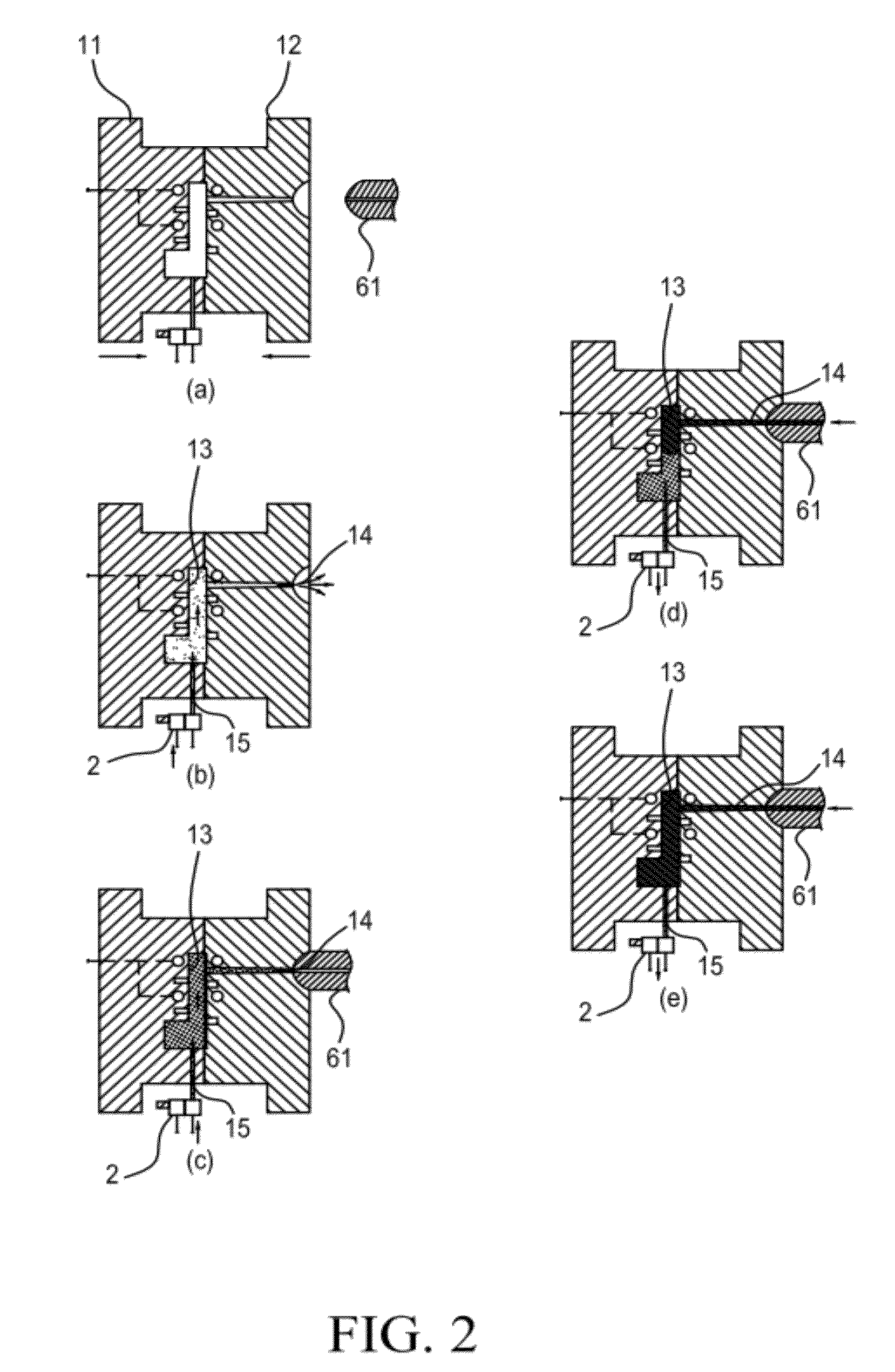
[0017]By the configuration of the counterpressure gas supplying device and the high-temperature gas supplying device in the apparatus of the present invention while enabling the two to work cooperatively, the mold cavity can be heated by the high-temperature gas from the high-temperature gas supplying device while the counterpressure gas supplying device is enabled to provide a counterpressure to the mold during a supercritical fluid (SCF) microcellular injection molding process, and thereby, not only the surface quality of a product resulting from the injection molding process can be improved, but also the size of the forms to be formed as well as the distribution evenness of the forms being produced in the injection molding process are enhanced so that the resulting product of the injection molding process can have better surface quality and proper foam size.

Problems solved by technology

Despite of the aforesaid advantages, the products produced by the MuCell process generally have poor surface appearance.

Method used


Image

  • Apparatus for controlling counterpressure and temperature in mold cavity
  • Apparatus for controlling counterpressure and temperature in mold cavity
  • Apparatus for controlling counterpressure and temperature in mold cavity

Examples


Embodiment Construction

[0039]For your esteemed members of reviewing committee to further understand and recognize the fulfilled functions and structural characteristics of the invention, several exemplary embodiments cooperating with detailed description are presented as the follows.

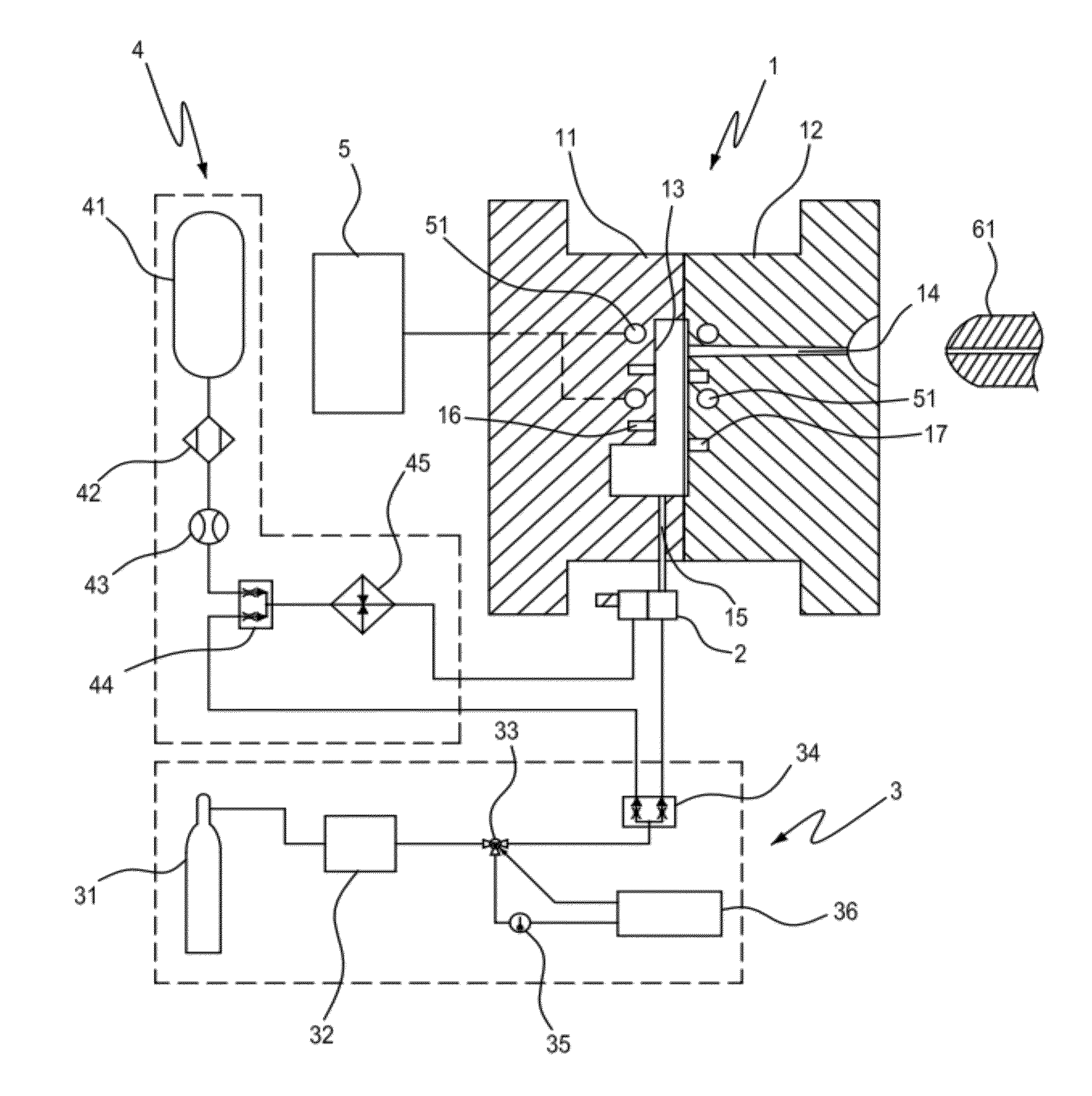
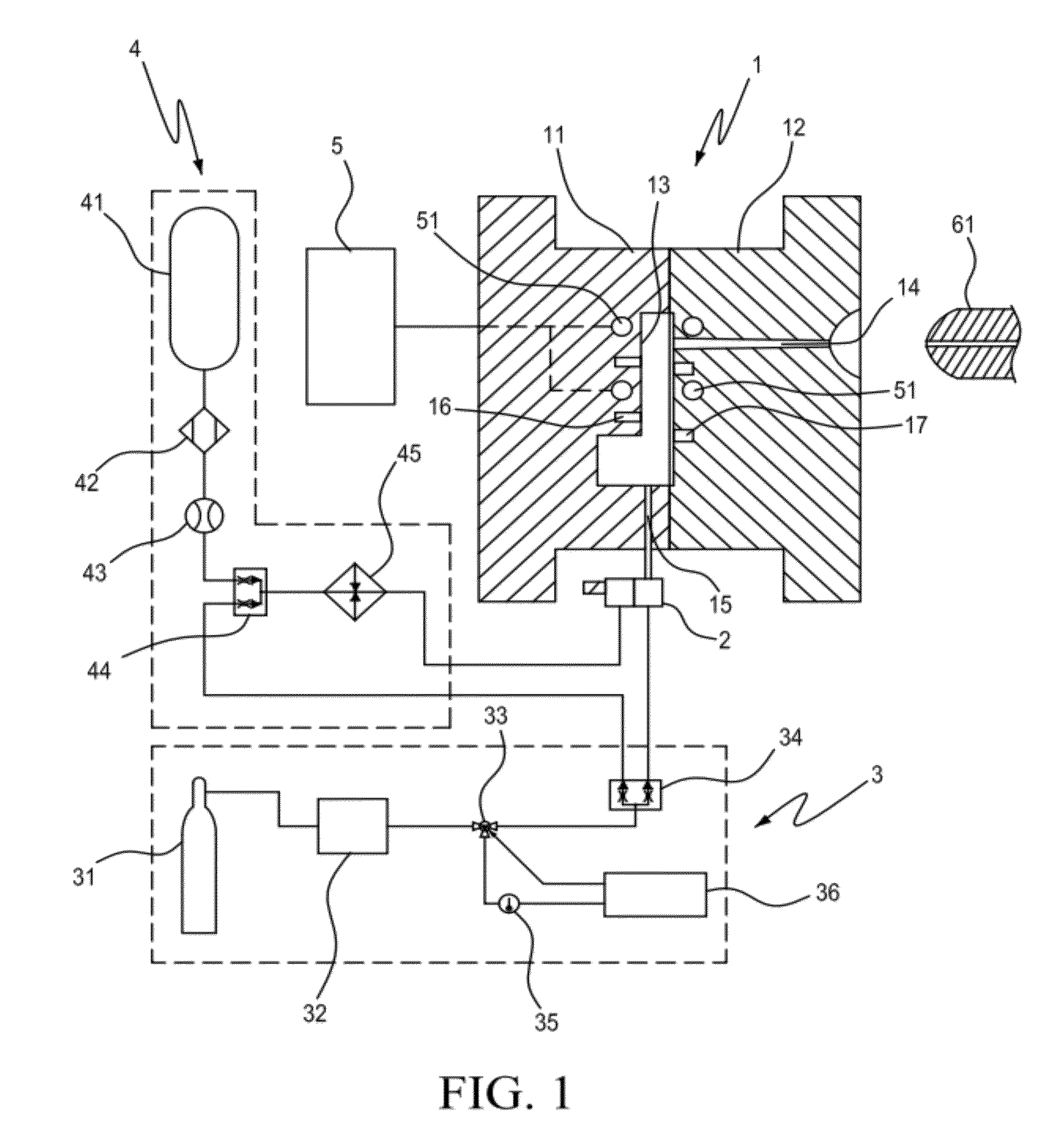
[0040]Please refer to FIG. 1, which is a schematic diagram showing an apparatus for controlling gas counterpressure and cavity temperature according to an embodiment of the invention. As shown in FIG. 1, an apparatus for controlling counterpressure and temperature of mold cavity is primarily composed of: a mold 1, a logic control valve 2, a counterpressure gas supplying device 3 and a high-temperature gas supplying device 4.

[0041]The mold 1, being composed of two mold-halves 11, 12 that can be controlled to open and close, has a runner 14 and an air passage 15 that are configured for communicating with a mold cavity formed inside the mold 1 while the two mold-halves 11, 12 are closed.

[0042]In FIG. 1, an end of the runner 14 th...


PUM

PropertyMeasurementUnit
Temperatureaaaaaaaaaa
Pressureaaaaaaaaaa
Mold temperatureaaaaaaaaaa

Abstract

A counterpressure / temperature control apparatus, comprises: a mold, having a runner and an air passage, both coupled to a mold cavity inside the mold; a logic control valve, coupled to the air passage for controlling a high-temperature gas or / and a counterpressure gas to flow in and out the mold cavity; a counterpressure gas supplying device, for supplying the counterpressure gas to the mold cavity through the logic control valve; and a high-temperature gas supplying device, for supplying the high-temperature gas to the mold cavity through the logic control valve; wherein the mold cavity is heated by the high-temperature gas, while subjecting the same to a counterpressure provided from the counterpressure gas supplying device during an injection molding process, and thereby, not only the surface quality of a product resulting from the injection molding process can be improved, but also the size of foams and the distribution evenness thereof are enhanced.

Description

FIELD OF THE INVENTION[0001]The present invention relates to a technology of plastic injection molding, and more particularly, to an apparatus for controlling gas counterpressure and cavity temperature in a supercritical fluid (SCF) microcellular injection molding process (MuCell process).BACKGROUND OF THE INVENTION[0002]Injection molding is a manufacturing process for producing parts from both thermoplastic and thermosetting plastic materials, which is becoming more and more popular in plastic industry. In response to the quest for advanced and diversified product design and the thend for producing smaller, lighter and more delicate products with satisfactiry aesthetic and functional results, there are a diversity of plastic injetion molding processes being developed. Especially for producing exterior parts for automobiles, electronic devices or household eletric appliances that are generally large in volume but should still be built the lighter the better while maintaining good me...

Claims


Application Information

Patent Timeline
IPC IPC(8): B29C35/04
CPCB29C35/007B29C44/348B29C44/105B29C45/1732B29C2045/1722B29C2045/7375B29C2045/7393B29C2945/76301
Inventor CHEN, SHIA-CHUNGHSU, PING-SHUNCHANG, JEN-ANHWANG, SHYH-SHINTSENG, CHIA-YEN
Owner CHUNG YUAN CHRISTIAN UNIVERSITY
Learn More