Rotary encoder and method of assembling the same
- Summary
- Abstract
- Description
- Claims
- Application Information
AI Technical Summary
Benefits of technology
Problems solved by technology
Method used
Image
Examples
first embodiment
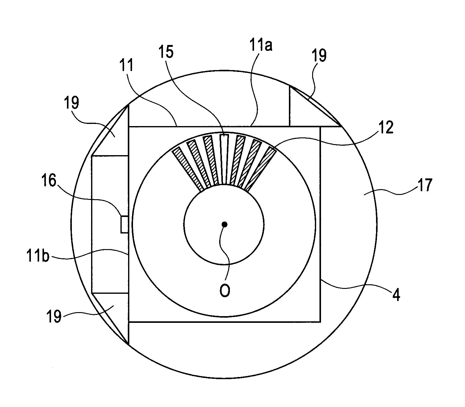
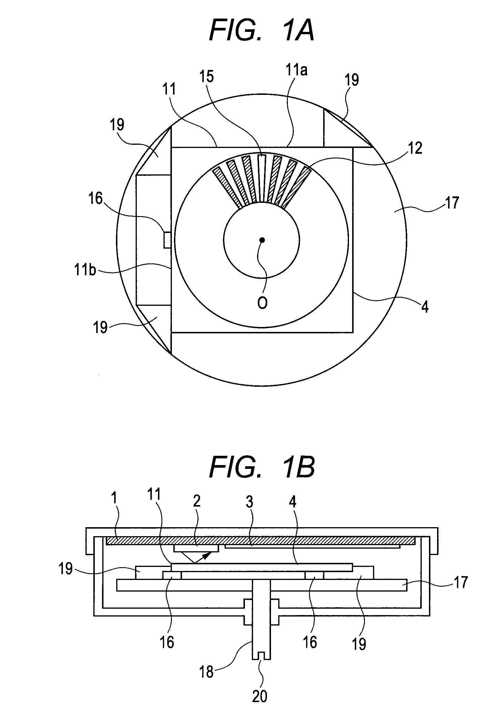
[0027]FIGS. 1A and 1B are a main portion top view and a partial side sectional view, respectively, illustrating a rotating unit of the rotary encoder according to the present invention. In this embodiment, the rotary scale 4 has a square outer shape and is made of silicon (Si). The rotary scale 4 is of a reflecting type having silicon as a base material, using aluminum for a reflection film, and being fabricated by a semiconductor manufacturing process including deposition, exposure, etching, etc. The square rotary scale 4 is adhered to three projections19 having taller height provided on the hub 17 as a rotating unit made of a resin under a state in which the rotary scale 4 is butted against and aligned with the three projections 19. The shaft (rotating shaft) 18 made of a metal is press-fitted into the hub 17.
[0028]The rotary scale 4 is provided with the continuous patterns 12 and the discontinuous portion (discontinuous pattern) 15, for detecting the rotation information. The dis...
fourth embodiment
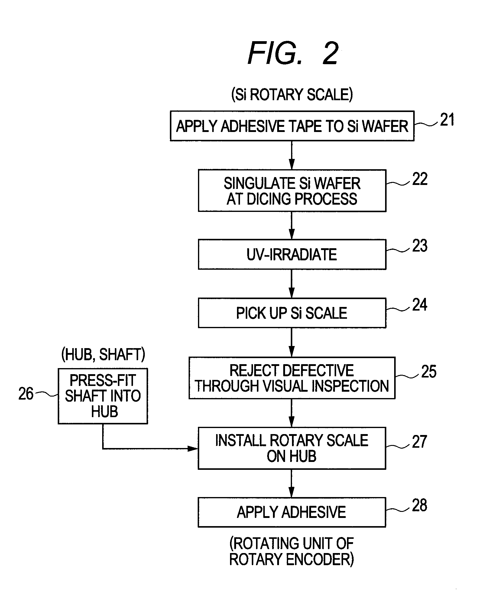
[0038]Hereinafter, a method of assembling a rotary encoder according to the present invention is described. The method of assembling the rotary encoder of the present invention is performed with reference to an orientation flat 32 of the silicon wafer 31. The predetermined pattern including the continuous patterns 12 and the discontinuous pattern (rotational angle original point) 15 is formed with reference to the pattern center (rotation center), and the rotary scale having a polygonal outer shape is cut out. The rotational angle original point is defined with reference to the at least one side 11a of the sides of the polygonal outer shape. The rotary scale 4 thus cut out is mounted to the hub 17, which is to rotate coaxially with the rotary scale 4, in such a manner that the rotary scale 4 abuts the projections 19 for positioning provided on the hub 17, so as to assemble the rotary encoder.
[0039]Position information (positional relationship) is measured among two sides 11a, 11b of...
fifth embodiment
[0047]In a method of assembling a rotary encoder according to the present invention, the positional relationship is measured between the rotating shaft 18 and the projections 19 for butting the rotary scale with respect to the shaft center of the hub 17. In this case, the rotary scale is offset in a direction to compensate a displacement amount thus determined, and subsequently the rotary scale is cut from a silicon wafer so as to assemble the rotary encoder.
[0048]FIG. 10 is an explanatory diagram illustrating the method of assembling the rotary encoder according to the fifth embodiment of the present invention. In FIG. 10, Xh denotes a distance between the center of the hub 17 and the butting portion of the projection 19 in an X-axis direction, and Yh denotes a distance between the center of the hub 17 and the butting portion of the projection 19 in a Y-axis direction. Xs denotes a distance between the center of the rotary scale 4 and the butting portion of the projection 19 in the...
PUM
| Property | Measurement | Unit |
|---|---|---|
| Angle | aaaaa | aaaaa |
Abstract
Description
Claims
Application Information
 - R&D
- Intellectual Property
- Life Sciences
- Materials
- Tech Scout
- Unparalleled Data Quality
- Higher Quality Content
- 60% Fewer Hallucinations
Browse by: Latest US Patents, China's latest patents, Technical Efficacy Thesaurus, Application Domain, Technology Topic, Popular Technical Reports.
© 2025 PatSnap. All rights reserved.Legal|Privacy policy|Modern Slavery Act Transparency Statement|Sitemap|About US| Contact US: help@patsnap.com


